HO"I'E; 3,p ece ts assemby s Sc}__ doo_'s <p to
a/'_,d t_c_ d _g 7 f<i_ell6 _s@ses t}gt At_ ex/et_s et_
?o_'8?<:_et do®_'s says abe
1. Set power head so that front panel (with end
of shaft and rail attachment flange) is facing up.
Fig. 1-1.
I_O'TE: f yo_/_sve _/'t,s _y_:_e(it_w't _{_:_ Stop skp
tt,_p 2
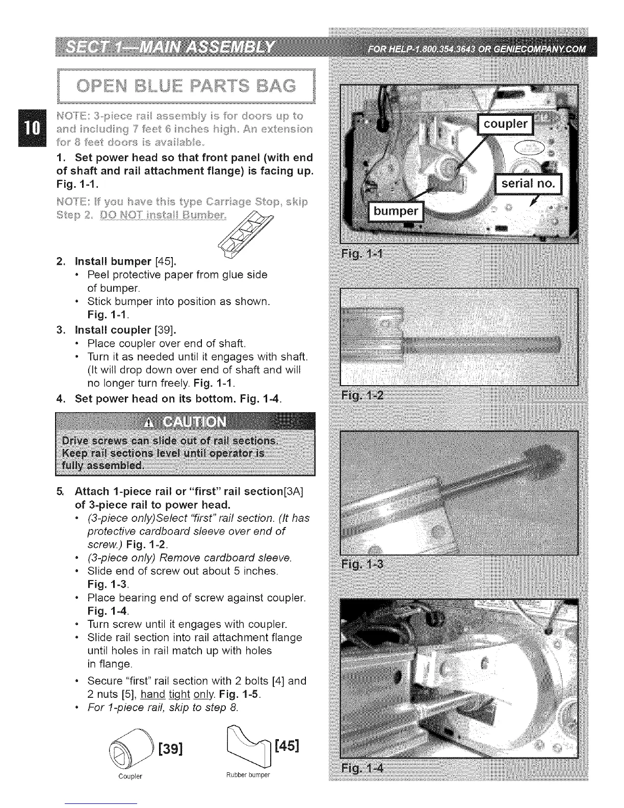
2. Install bumper [45].
* Peel protective paper from glue side
of bumper.
* Stick bumper into position as shown.
Fig. 1-1.
3. Install coupler [39].
* Place coupler over end of shaft.
* Turn it as needed until it engages with shaft.
(it will drop down over end of shaft and will
no longer turn freely. Fig. 1-1.
4. Set power head on its bottom. Fig. 1-4.
Attach 1-piece rail or "first" rail section[3A]
of 3-piece rail to power head.
* (3-piece only)Select "first" raft section. (It has
protective cardboard sleeve over end of
screw.) Fig. 1-2.
* (3-piece only) Remove cardboard sleeve.
* Slide end of screw out about 5 inches.
Fig. 1-3.
* Place bearing end of screw against coupler.
Fig. 1-4.
* Turn screw until it engages with coupler.
* Slide rail section into rail attachment flange
until holes in rail match up with holes
in flange.
* Secure "first" rail section with 2 bolts [4] and
2 nuts [5], hand tight only. Fig. 1-5.
* For 1-piece rail, skip to step 8.
Coupler
[39]
[4s]
Rubber bumper
 Loading...