7. Attach "end" rail section [3C].
• Attach "end" rail in same way as "middle" rail
(step 5). ("End" rail section screw has "hook"
on one end only.)
8. Flip power head/rail assembly over (upside
down), so that entire length of screw is visible
from above.
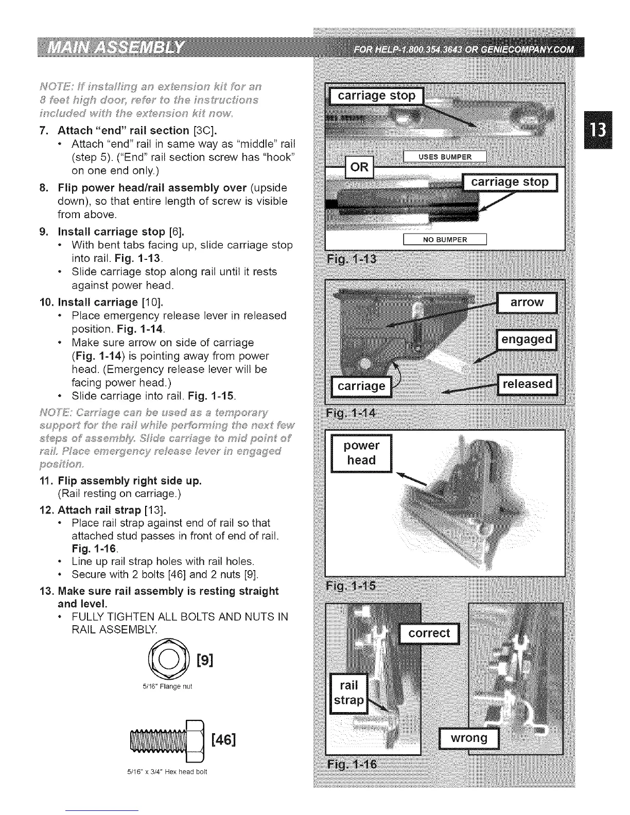
9. install carriage stop [6].
• With bent tabs facing up, slide carriage stop
into rail. Fig. 1-13.
• Slide carriage stop along rail until it rests
against power head.
10. install carriage [10].
• Place emergency release lever in released
position. Fig. 1-14.
• Make sure arrow on side of carriage
(Fig. 1-14) is pointing away from power
head. (Emergency release lever wilt be
facing power head.)
• Slide carriage into rail. Fig. 1-15.
NOFi_iJ!/Oa_%Q:e oa,,',,be t_;'ed_s s _:_mp®p;s_/
_?#L £V#c.®®me;s[?®oc}f ;,'<#_t_ssehive;" M ®g#g®d
11. Flip assembly right side up.
(Rail resting on carriage.)
12. Attach rail strap [13].
• Place rail strap against end of rail so that
attached stud passes in front of end of rail.
Fig. 1=16.
• Line up rail strap holes with rail holes.
• Secure with 2 bolts [46] and 2 nuts [9].
13. Make sure rail assembly is resting straight
and level.
• FULLY TIGHTEN ALL BOLTS AND NUTS IN
RAIL ASSEMBLY.
[91
5/16" Flange nut
[4S]
5/16" x 3/4" Hex head bolt
power
head
 Loading...