1. Check local building codes.
* Does building code require permanent wiring?
- If not, skip to step 9.
2. Remove power from circuit.
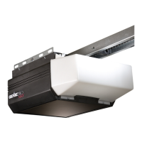
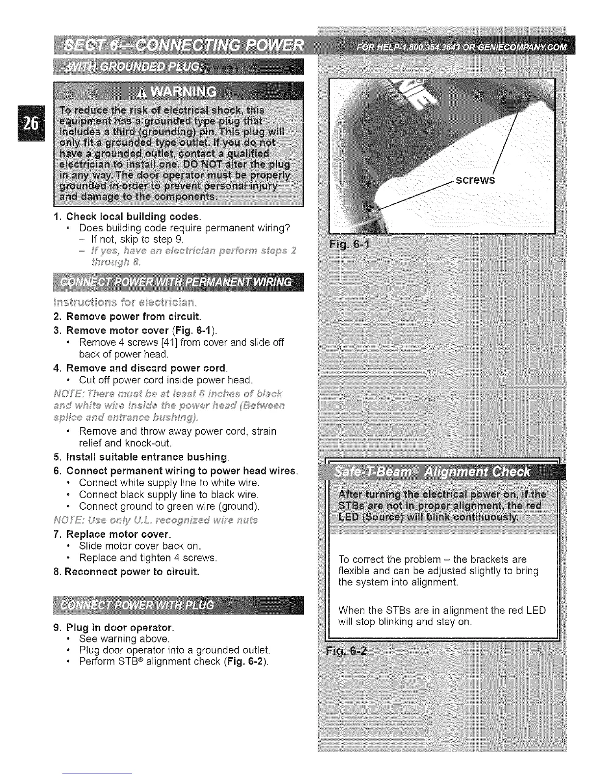
3. Remove motor cover (Fig. 64).
. Remove 4 screws [41] from cover and slide off
back of power head.
4. Remove and discard power cord.
. Cut off power cord inside power head.
. Remove and throw away power cord, strain
relief and knock-out.
5. Install suitable entrance bushing.
6. Connect permanent wiring to power head wires.
. Connect white supply line to white wire.
• Connect black supply line to black wire.
• Connect ground to green wire (ground).
NO_!!! U\se ®n_;/ U L_ ecoqn?_;,d wh-e nuJ_;
7. Replace motor cover.
. Slide motor cover back on.
• Replace and tighten 4 screws.
8. Reconnect power to circuit.
9. Plug in door operator.
. See warning above.
. Plug door operator into a grounded outlet.
. Perform STB ®alignment check (Fig. 6-2).
To correct the problem - the brackets are
flexible and can be adjusted slightly to bring
the system into alignment.
When the STBs are in alignment the red LED
will stop blinking and stay on.
 Loading...