BLIZZARD 400-800 C ENC 28 532104 - Rev.A
8
46
Translation of the original instructions
ENGLISH
7.8 SET-UP
!
During Setup, the photocells and the safety edges are disabled; prevent
transit in the area of movement of the gate.
Li
The flashing S0 code on the display indicates that the Setup procedure
must be carried out.
Any Bus devices that are connected are registered during the Setup
procedure.
The Setup procedure can be interrupted by using the STOP command.
If a MASTER-SLAVE configuration is used, carry out the Setup procedure
after having read § 10.
1. Bring the gate to its halfway position following the instructions
in § 5.5. Restore automatic operation.
2. Go to function
tL in Basic Programming.
3. Press and hold down the
+ and
-
buttons until the gate starts
to close.
4. Release the
+ and
-
buttons. The Setup procedure will continue
independently. Check the following conditions:
DISPLAY PHASE
S1
Gate closing movement
S2
Closing limit switch engaged.
S3
Gate opening movement.
S4
Opening limit switch engaged.
01
Setup procedure completed. Gate open.
8. FINAL OPERATIONS
RISKS
PERSONAL PROTECTIVE EQUIPMENT
1. Make sure that the forces generated by the leaf are within the
limits permitted by the current regulations. Use an impact force
tester in accordance with standards EN 12453 and EN 12445. For
non-EU countries, of there are no specific local regulations, the
force must be less than 150 N.
2. Check that the maximum force required to move the leaf by hand
is less than 150 N.
3. Highlight all areas with adequate warning signs in which there
are still residual risks, even if all possible safety measures having
been adopted.
4. Place a “DANGER, AUTOMATICALLY CONTROLLED” sign in a promi-
nent position on the gate.
5. Attach the CE marking to the gate.
6. Fill out the EC declaration of conformity and the system register.
7. Give the EC Declaration, the system register with the maintenance
plan and the instructions for use of the automation system to the
system owner/operator.
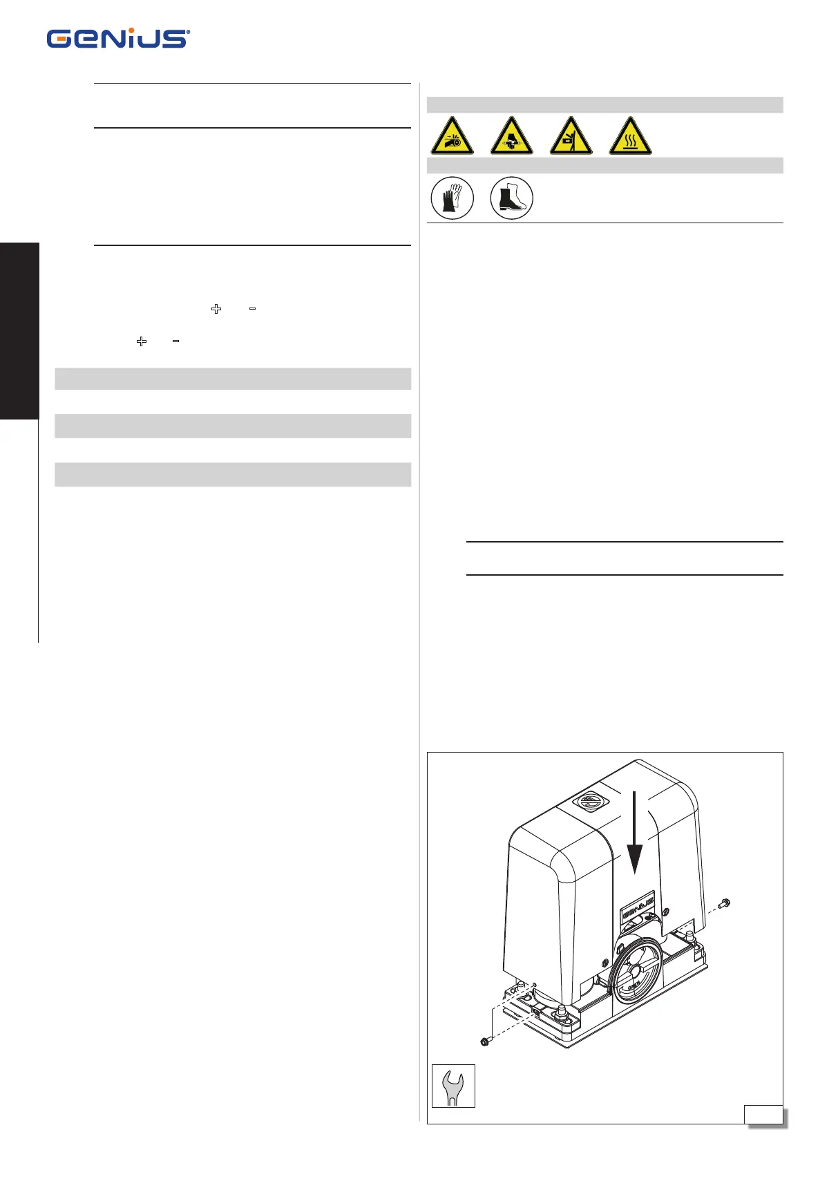
INSTALLING THE CASING
!
Install the cover 46: using the M5X12 hexagonal head or Allen
screws provided.
 Loading...