EasyManuals Logo

GeoVision GV-AS100 Hardware Installation Guide

GeoVision GV-AS100
131 pages
To Next Page IconTo Next Page
To Previous Page IconTo Previous Page
Page #115 background imageLoading...
Page #115 background image
GV-AS400 Controller
105
3
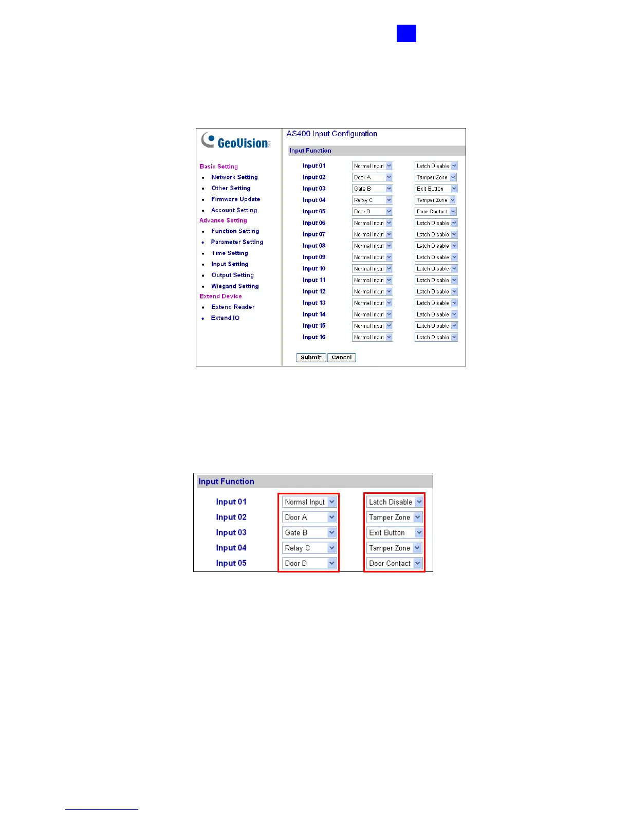
3.4.3.D Input Function
In the left menu, click Input Function. This AS400 Input Configuration page appears.
Figure 3-21
Here you can define each sensor input that is connected to GV-AS400 and select the most
fitting Input Type (No. 1, Figure 3-22) and Input Function (No. 2, Figure 3-22) to describe
the sensor input. Through the sensor input, an alarm event can be detected and the event
may also trigger the alarm.
Figure 3-22
1. Input Type: Configure the input type. Input Type defines the type of sensor that is
connected to the input of GV-AS400. Options available for the input type change based
on your settings of Door/Gate # in the Function Setting page (Figure 3-17).
2. Input Function: Configure the input function. Options available for the input function
change based on the settings of Input Type above.
1 2

Table of Contents

Other manuals for GeoVision GV-AS100

Questions and Answers:

Question and Answer IconNeed help?

Do you have a question about the GeoVision GV-AS100 and is the answer not in the manual?

GeoVision GV-AS100 Specifications

General IconGeneral
InterfaceRS-485
Case designHousing
Built-in UPS-
Number of users40000 user(s)
Maximum number of doors1 door(s)
Number of Wiegand readers supported1
Power consumption200 mA
Operating temperature (T-T)0 - 65 °C
Operating relative humidity (H-H)10 - 90 %
Weight and Dimensions IconWeight and Dimensions
Depth27 mm
Width96 mm
Height137 mm
Weight250 g

Related product manuals