GV-AS200 Controller
61
2
2.2.5 Connecting the Power
After all wiring is complete, power on GV-AS200.
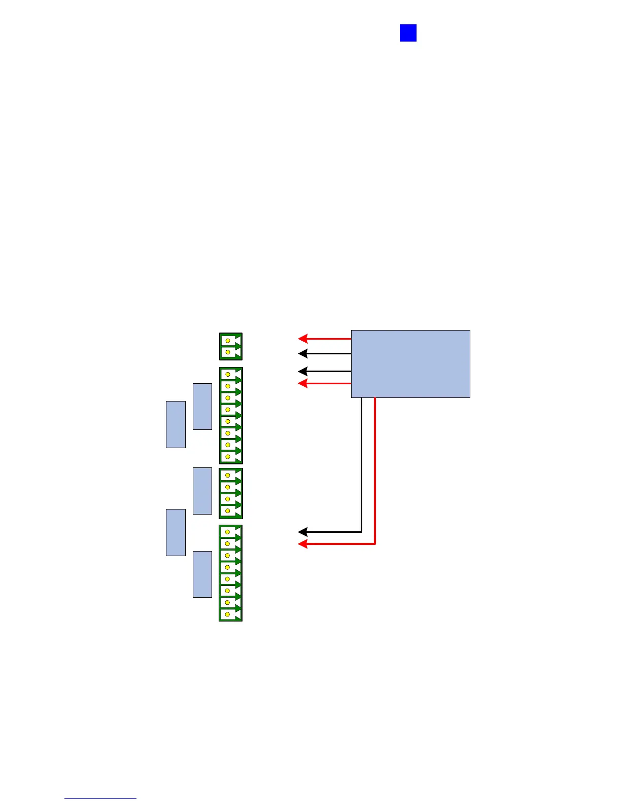
1. Plug one end of the supplied power cable into the 6-pin connector on the power
converter, and the other end into the three power connectors on the GV-AS200 module:
• Power Connectors: 12V DC +/ -
• Door A Power Connectors: Power +/-
• Door B Power Connectors: Power +/-
The black line of the power cable represents negative (-); the red line of the power cable
represents positive (+).
Output Input Output
Door B Door A
Power +
DC 12V+
DC 12V -
Power -
Power +
Power Cables
Power Converter
Power Cables
Power -
Output Input Output
Door B Door A
DC 12V+
DC 12V -
Power -
Power +
Power Cables
Power Converter
Power Cables
Figure 2-13
2. Power on the power converter. Plug one end of the supplied power cable into the 2-pin
connector on the power converter, and the other end into the power source.

 Loading...


