32
Insert the chain end piece with pin and quick-release fastener (7) into the ob-
long hole of the bracket OW (5). If necessary, extend the chain.
Let the quick-release fastener (7) latch in at the bracket OW (5).
1 = Stroke 100 mm 2 = Stroke 200 mm 3 = Stroke 300 mm 4 = Stroke 400 mm
6.4 Fastening means
Window
type
Fastening means Drill Ø
Light alloy Slotted pan head screw 4.2 x L DIN ISO 7049
Screw must pass through min. 1.8 mm prole cladding
3.5 mm
Plastic Slotted pan head screw 4.2 x L DIN ISO 7049
Screw must pass through min. 2 prole walls
3.5 mm
Wooden Round head wood screw 4.5 x L DIN 96
Alternatively: SPAX countersunk screw 4.0 x L
(2.0 mm)
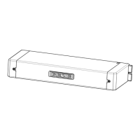
7 Electrical connections E740 Syncro
The cable supplied with the drive has a length of 5.0 metres (± 5%) and its properties are designed
so that the electrical safety regulations are observed. If the distance between the drive and the
operating elements exceeds 5.0 metres, only the conductors for the power supply can be extended.
ATTENTION: The RED and WHITE conductors must not be extended and are to be connected to
the junction box at a maximum distance of 5 metres. At greater distances reliable transferring
of the synchronisation signal is no longer ensured.
The electrical connection of the two conductors is to be carried out with a suitable terminal (not
included). A secure connection with a perfect electrical contact is decisive for the signal transfer.
Insert
Latch
e.g.:
Set the stroke: Set the stroke by turning the stroke adjustment switch.
Carry out the stroke setting in the closing position of the drive.