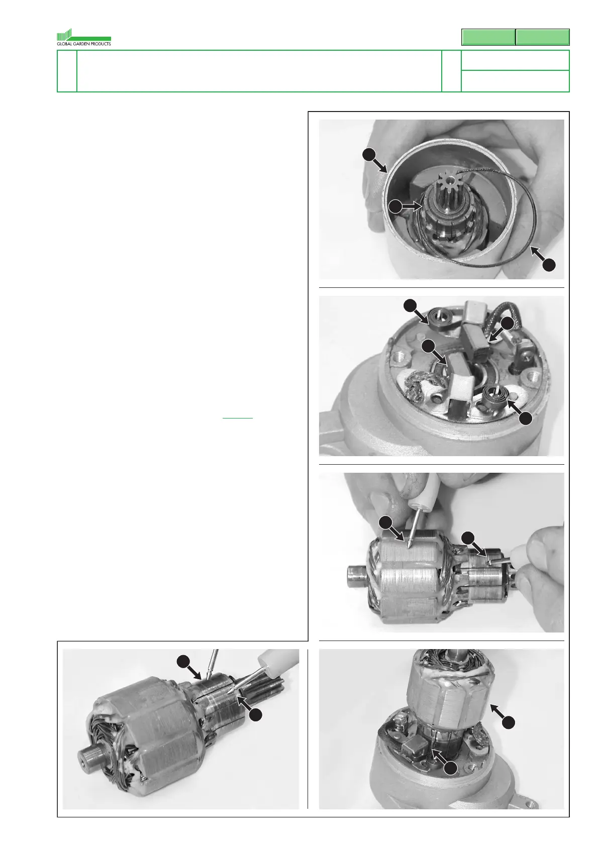
24 Check the condition of the brushes (24) and rel-
ative springs (25).
25 Extract the rotor (26) and make the electrical
checks using a universal tester in Ohmmeter
mode:
– with one test prod (27) on the rotor armature
and the other (28) on the commutator bars the
instrument should register that there is no
passage of current;
– with the test prod (29) on the commutator
bars, the instrument should register that there
is no passage of current between any of the
bars.
The starter motor must be replaced if this is not
so.
26 On assembly, take care to reposition the brush-
es (24) correctly with respect to the rotor bars
(26) and refit the sealing ring (23).
27 Remount the starter motor [
6.11.A].
D) Checking and adjusting the recharge
alternator
31 Use an ammeter clamp (31) to check the
recharge values in the following conditions of
use:
Battery charged - engine at minimum = 0,35-0,40 A
Battery charged - engine at maximum = 0,45-0,50 A
Battery discharged - engine at minimum = 0,40-0,45 A
Battery discharged - engine at maximum = 0,45-0,55 A
6.11.0 - ELECTRICAL STARTING SYSTEM
AND RECHARGE ALTERNATOR
3 / 4
SERVICE MANUAL
page
from
2007 to ••••
4/2007© by GLOBAL GARDEN PRODUCTS
SV200 R200
21
23
24
25
24
25
26
27
28
29
29
26
23
 Loading...