If different values are registered, make the
checks described below and, if a satisfactory
result is not obtained, the alternator must be
replaced.
32 Remove the starting system [
6.2.A].
33 Remount the tank [
6.1.A].
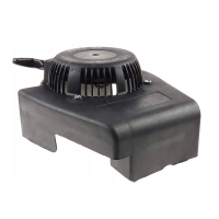
34 Remove the conveyor (32).
35 Loosen the two screws (33) securing the alter-
nator coil (34), release the brake manually and
rotate the flywheel (35) until the magnetic
inserts are lined up with the poles of the coil
core (34).
36 Insert a 0.35 mm thickness gauge (36) between
the magnet flywheel (35) and the coil poles.
Push the coil until the poles come in contact
with the thickness gauge and secure both
screws (33). Tighten the screws remembering
that the air gap must be between 0.25 and 0.40
mm.
37 Remount the conveyor (31).
38 Remount the tank [
6.1.A].
39 Remount the starting system [
6.2.A].
Tightening torques
4
Motor fixing screws ............................ 8-10 Nm
Technical information
Recharge values ........................... 0,45-0,55 Amps
Special equipment
-
Universal tester
- Ammeter clamp
6.11.0 - ELECTRICAL STARTING SYSTEM
AND RECHARGE ALTERNATOR
4 / 4
SERVICE MANUAL
page
from
2007 to ••••
4/2007© by GLOBAL GARDEN PRODUCTS
SV200 R200
31
36
35
34
33
33
32
 Loading...