Installation Manual Series CF (excluding encapsulated screw compressors) 23042013 Rev. A / May 2007 21 of 60
4.9 Fitting instructions
4.9.1 Coupling
The connection element between compressor
and driving motor shall be a well aligned flexible
coupling that should be balanced according to
following balancing grade.
Couplings should be used with a balancing grade
of G 2.5 to DIN ISO 1940 respectively
Q 2.5 to VDI 2060, balanced according to the
“half-key convention” to DIN ISO 8821. According
to this, a half key corresponding to the contour of
the inside diameter is inserted in the groove
when balancing.
It has to be paid attention that only couplings with
a balancing grade of G 2.5 or Q 2.5 or better are
utilized.
A insufficient balanced coupling might lead to
damages of bearings and gears and so to de-
struction of the whole compressor unit.
To avoid additional unbalance force, the length of
the coupling hub should correspond to the length
of the driving journal (see section „Technical
data“).
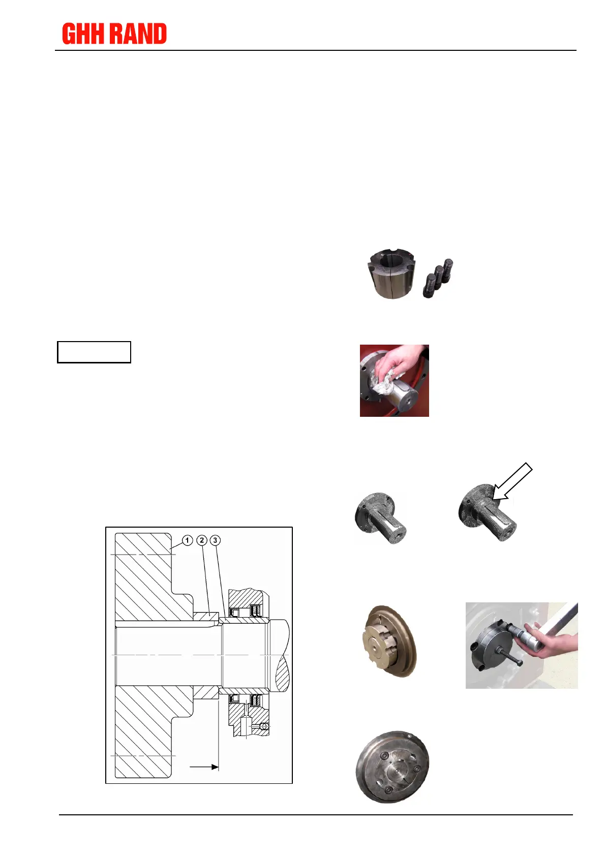
In case of a shorter coupling hub (1) a spacer
ring (2) shall be fitted between coupling hub (1)
and bearing ring (3), to axially fix the bearing ring
and to avoid an unbalanced protruding key.
The coupling has to be designed for every par-
ticular and individual case according to the speci-
fication of the calculated rotary oscillation (see
also section
4.4).
Sufficient axial clearance has to be considered.
Adjustment of coupling has to be ensured by
means of dial indicators.
Transmission of axial forces onto the drive pin is
not allowed.
Example: fitting of coupling
1. parts to be fitted
2. Preparation cleaning
3. Steps of fitting
a) b)
c) d)
e)
Depending on
length of coupling
a spacer ring might
be needed.