Installation Manual Series CF (excluding encapsulated screw compressors) 23042013 Rev. A / May 2007 7 of 60
3 Description of product and accessories
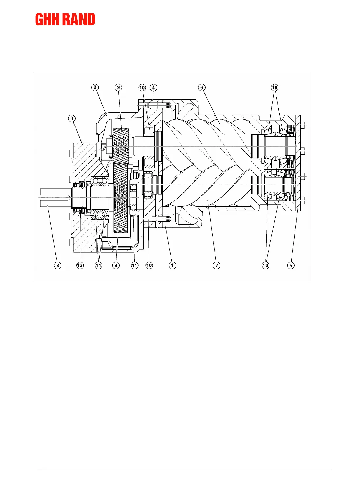
3.1 Main assemblies of the compressor
Sectional drawing of a screw compressor as an example
Main components: Rotors: Seals:
1 Rotor casing 10 Rotor bearing 12 Shaft seal
2 Gear casing 11 Drive shaft bearing
3 Gear case cover
4 Bearing casing
5 Cover
6 + 7 Rotor pairs (Mail + Fe-
male)
8 + 9 Set of wheels (driving
wheel with shaft + pin-
ion)