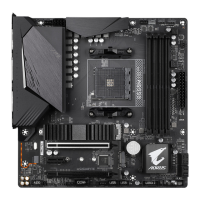
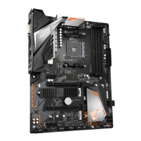
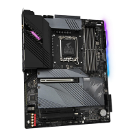
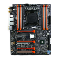
- 33 -
The front panel design may differ by chassis. A front panel module mainly consists of power
switch, reset switch, power LED, hard drive activity LED, speaker and etc. When connecting
your chassis front panel module to this header, make sure the wire assignments and the pin
assignments are matched correctly.
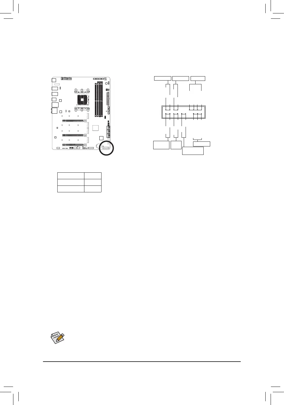
13) F_PANEL (Front Panel Header)
Connectthepowerswitch,resetswitch,speaker, chassis intrusionswitch/sensorandsystemstatus
indicator on the chassis to this header according to the pin assignments below. Note the positive and
negative pins before connecting the cables.
System Status LED
S0 On
S3/S4/S5 Off
• PW (Power Switch):
Connectstothepowerswitchonthechassisfrontpanel.Youmaycongurethewaytoturnoffyour
system using the power switch (refer to Chapter 2, "BIOS Setup," "Settings\Platform Power," for more
information).
• SPEAK (Speaker):
Connects to the speaker on the chassis front panel. The system reports system startup status by
issuing a beep code. One single short beep will be heard if no problem is detected at system startup.
• HD (Hard Drive Activity LED):
Connects to the hard drive activity LED on the chassis front panel. The LED is on when the hard drive
is reading or writing data.
• RES (Reset Switch):
Connects to the reset switch on the chassis front panel. Press the reset switch to restart the computer
ifthecomputerfreezesandfailstoperformanormalrestart.
• CI (Chassis Intrusion Header):
Connectstothechassisintrusionswitch/sensoronthechassisthatcandetectifthechassiscover
hasbeenremoved.Thisfunctionrequiresachassiswithachassisintrusionswitch/sensor.
• NC: No connection.
• PLED/PWR_LED (Power LED):
Connects to the power status indicator on the chassis front panel. The LED
is on when the system is operating. The LED is off when the system is in
S3/S4sleepstateorpoweredoff(S5).
Power LED
1
2
19
20
CI-
CI+
PWR_LED+
PLED-
PW-
SPEAK+
SPEAK-
PLED+
PW+
HD-
RES+
HD+
RES-
Hard Drive
Activity LED
Reset
Switch
Chassis Intrusion
Header
Power Switch
Speaker
PWR_LED-
PWR_LED-
Power LED
NC
NC
 Loading...