User Guide
GD32E507Z-EVAL
22/43
5.10. ADC_Channel_Differential_mode
5.10.1. DEMO purpose
This demo includes the following functions of GD32 MCU:
Learn to use the ADC to convert analog signal to digital data
Learn to use ADC channel differential mode
5.10.2. DEMO running result
Download the program <10_ADC_Channel_Differential_mode > to the GD32E507Z-EVAL-
V1.0 board. Connect serial cable to USART0.
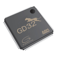
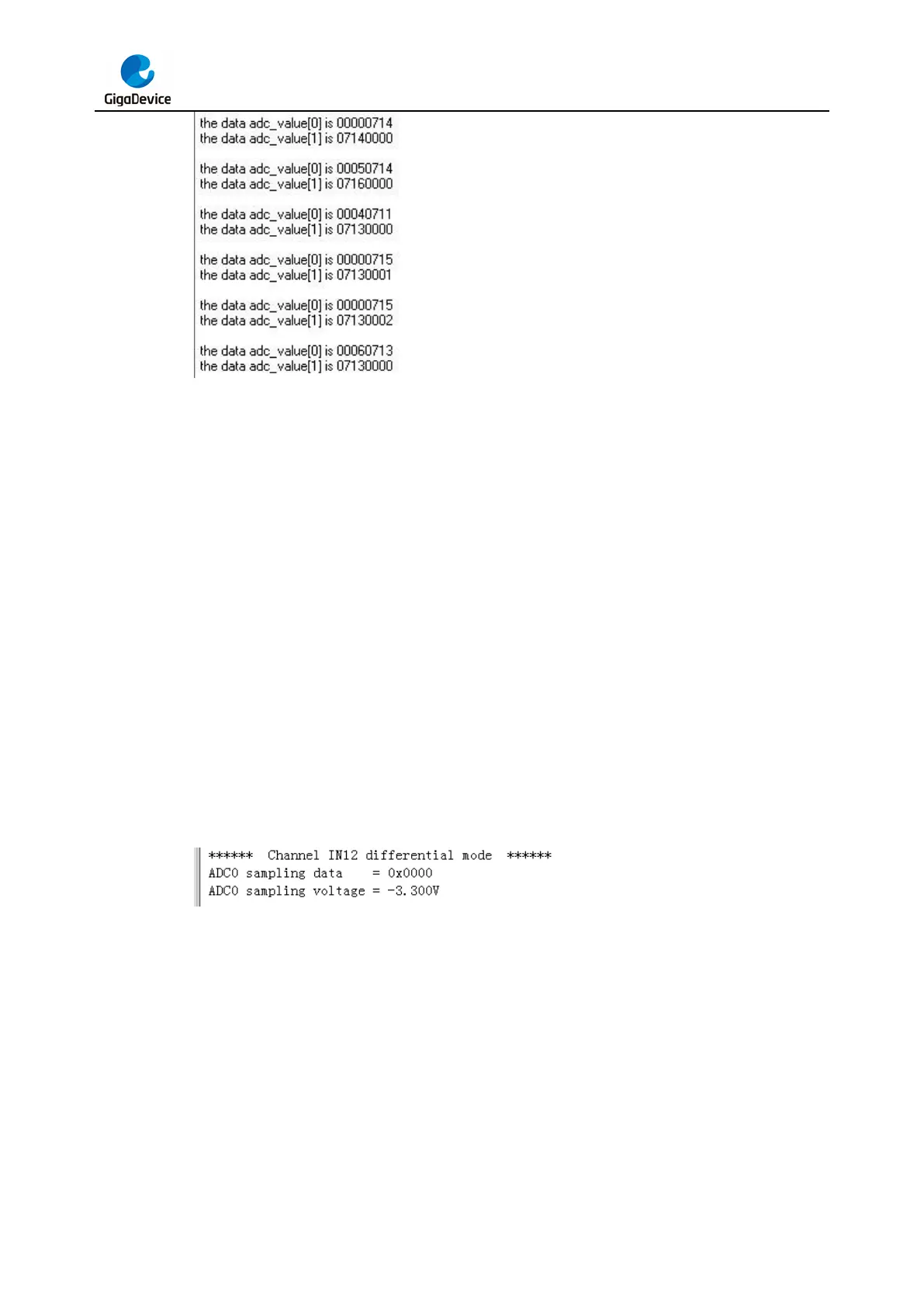
Software is the trigger source of ADC0, and the continuous function is enabled. ADC0_IN12
(PC2) is configured in differential input mode. The difference voltage between ADC0_IN12
(PC2) and ADC0_IN13 (PC3) is transmitted to array adc_value by DMA. When the program
is running, HyperTerminal displays the value of adc_value and the difference value of voltage.
5.11. DAC_Output_Voltage_Value
5.11.1. DEMO purpose
This demo includes the following functions of GD32 MCU:
Learn to use DAC to output voltage on DAC_OUT_0 output
 Loading...