User Guide
GD32E507Z-EVAL
8/43
3. Getting started
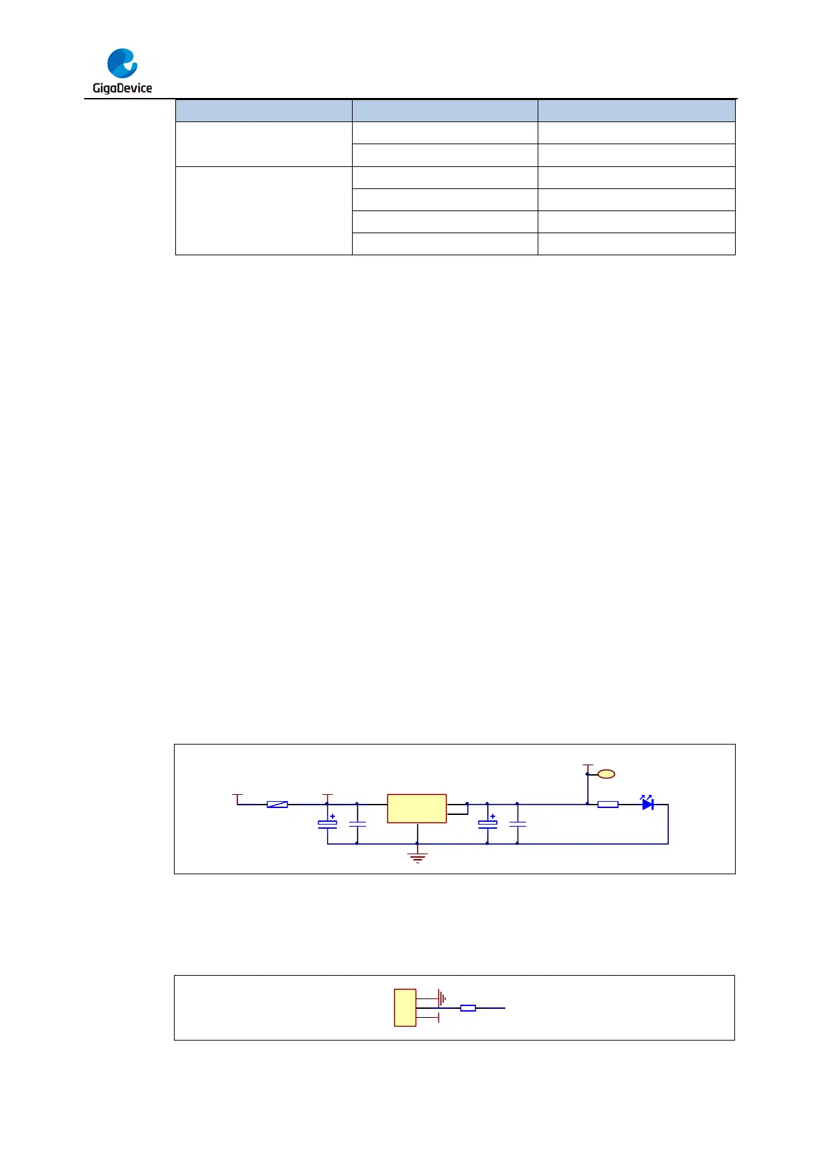
The EVAL board uses GD-Link Mini USB connecter to get power DC +5V, which is the
hardware system normal work voltage. A GD-Link on board is necessary in order to download
and debug programs. Select the correct boot mode and then power on, the LEDPWR will turn
on, which indicates the power supply is OK.
There are Keil version and IAR version of all projects. Keil version of the projects are created
based on Keil MDK-ARM 5.26 uVision5. IAR version of the projects are created based on IAR
Embedded Workbench for ARM 8.32.1. During use, the following points should be noted:
1. If you use Keil uVision5 to open the project. In order to solve the "Device Missing (s)"
problem, you can install GigaDevice.GD32E50x_DFP.1.3.0.pack.
2. If you use IAR to open the project, install IAR_GD32F50x_ADDON_1.3.0.exe to load the
associated files.
4. Hardware layout overview
4.1. Power supply
Figure 4-1. Schematic diagram of power supply
G
1
Vout
2
Vin
3
4
U2 AMS1117-3.3
E1
16V/10uF,AVX
E2
16V/10uF,AVX
C20
50V/0.1uF
C21
50V/0.1uF
+3V3
LEDPWR
LED0603
R7
470Ω
1
TP1
TP +3V3
+U5V
P1
SMD1210P005TF
+5V
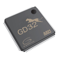
4.2. Boot option
Figure 4-2. Schematic diagram of boot option
R4
10KΩ
1
2
3
JP3
BOOT0
GND
BOOT0
+3V3