------------------------------------------------------------- Auto Ref/Keratometer GRK-7000
21
6. Installation of Equipment & Preparation of Measurem
ent
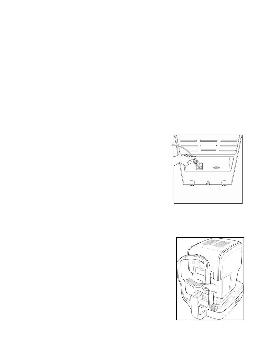
1. Release of Lock on Stage Section
Unlock the clamping bolt at the lower part of Chin-rest of the machine by
rotating it counterclockwise, and change the stag
e fixing lever behind the joystick to the direction
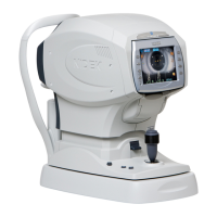
2. Connection of Power Cable
- Put GRK-7000 on the table.
- Insert the power cable into power connector a
t the bottom of the main body.
- After checking that the power of the machine i
s off, insert the power plug into the AC outlet (socket).
3. Inserting Chin Rest Paper
- Pull out the pushing pins at left/right sides.
- Insert the pushing pins into the holes at left/righ
t sides of the chin-rest paper.
- Stick the chin-rest paper inserted with the pushi
ng pins onto the Chin-rest.
[ Figure 5. Connection of Power Cable ]