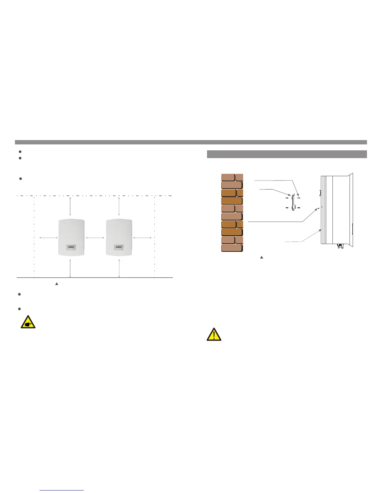
For 1 or more inverter installed, a minimum 12in clearance should be kept between each
inverter or other object. The bottom of the inverter should be 20in clearance to the
ground.
Visibility of the LED status indicator lights and the LCD located at the front panel of
the inverter should be considered.
Adequate ventilation must be provided if the inverter is to be installed in a confined space.
NOTE:
Nothing should be stored on or placed against the inverter.
Install on a wall or strong structure capable of bearing the weight.
Install vertically with a maximum incline of +/- 5°.If the mounted inverter is tilted to an
angle greater than the maximum noted, heat dissipation can be inhibited, and may result
in less than expected output power.
500mm
500mm
500mm
500mm 500mm
500mm
500mm
Figure 4.1 Inverter Mounting clearance
4. Installation4. Installation
Inverter should be mounted in a vertical position as shown in Figure 4.3. The steps to
mount the inverter on the wall are given as follows:
1. Locate the wall studs in the desired location and align the wall mount bracket over
the studs. Mark the mounting holes. For masonry walls, the mounting holes should be
for a suitable dynabolt type mounting system.
2. MAKE SURE BRACKET IS horizontal. Ensure that the A, B, C, and D mounting holes
(in Figure 4.3) are aligned with the wall's most secure points (e.g. wall studs in case of
clad building materials).
4.2 Mounting the Inverter
Please use suitable fixings for wall type (e.g. use dynabolts for brick, masonry, etc).
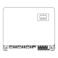
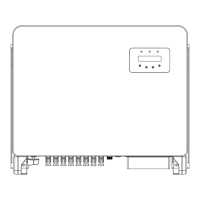
Figure 4.3 Inverter Mounting
WARNING:
Bracket must be mounted vertically on a vertical wall surface.
Bracket
M4×14 stainless steel screw
Inverter
Suitable fixing screws
.10. .11.
Figure 4.2 Inverter Mounting clearance