EEC4 Installation Manual
8
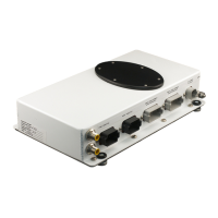
ENGINE CONNECTION
Throttle
Gear
Start
Interlock
ILLUSTRATION
make sure
rubber
gasket
is intact
when
connecting
DESCRIPTION
Connect the 3 pin plug into the appropriate con-
nection on the vessel adapter harness.
Connect the 2 DIN Gear connectors on the trans-
mission solenoids. Note that each plug is marked
“forward” or “reverse” — connect this to the correct
solenoid on the transmission.
Or . . . Connect the 2 FI Gear connectors on the
transmission solenoids. Note that each plug is
marked “forward” or “reverse” — connect this to
the correct solenoid on the transmission.
Connect the 2 pin start interlock plug to the appro-
priate connection on the engine (near the transmis-
sion).
Gear Connectors on
TCPM are colored gray
Gear Connector
on harness
Gear Connectors (2)
Throttle Connector
on harness
Throttle Connector
Start Interlock
Connector
Control System Enable
Connector
Throttle Connectors on
TCPM are colored black
Throttle & Transmission Harness
(each engine requires 1 harness)