See the photos below and on the next page for step-by-step instructions for connecting the
Control System Enable connections.
Section 1.0 — Installing the EEC4
9
IMPORTANT — When routing and connecting the throttle and gear harness, BE SURE TO:
Insert the plug completely into the receptacle on the control processor and the engine. You
should hear a “click” when the plug is fully inserted.
DO NOT route cables past any sharp edges!
ENGINE
CONNECTION
Control
System
Enable
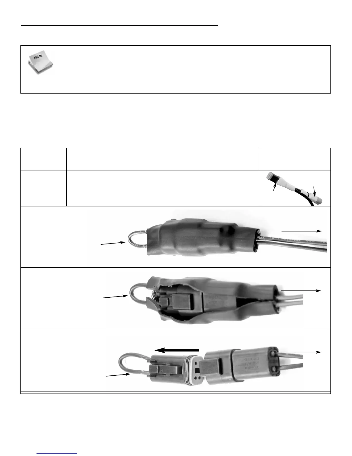
DESCRIPTION
Connect the 4 pin control system enable plug to the
appropriate connection on the vessel adapter harness. In
order to do this you will need to follow the steps below:
Locate control system plug from
engine
Cut & remove heat shrink
tubing
Remove existing jumper from
engine side connector
2
3
keyswitch
jumper
breakout
to vessel
adapter harness
piggy-back
connector
control system
enable plug
1
ILLUSTRATION
to vessel
adapter harness
to vessel
adapter harness
keyswitch
jumper
breakout
existing keyswitch
jumper breakout
remove jumper