Photo Electric Cell Wiring
Consult the installation instructions supplied by manufacturer of the Photo Electric Cell and determine
whether the contacts are normally open (N/O) or normally closed (N/C).
Always disconnect power to unit BEFORE making any setting changes.
CAUTION:
Photo Electric Cells are recommended as a supplementary safety system. If required, 12 or 24 VDC power
may be sourced from terminals 5 & 6 of J3. Ensure jumper JP2 is confi gured to match required voltage of
photo electric cell. Refer to page 11.
Glidermatic™
Commercial Door Operator
User Manual
9
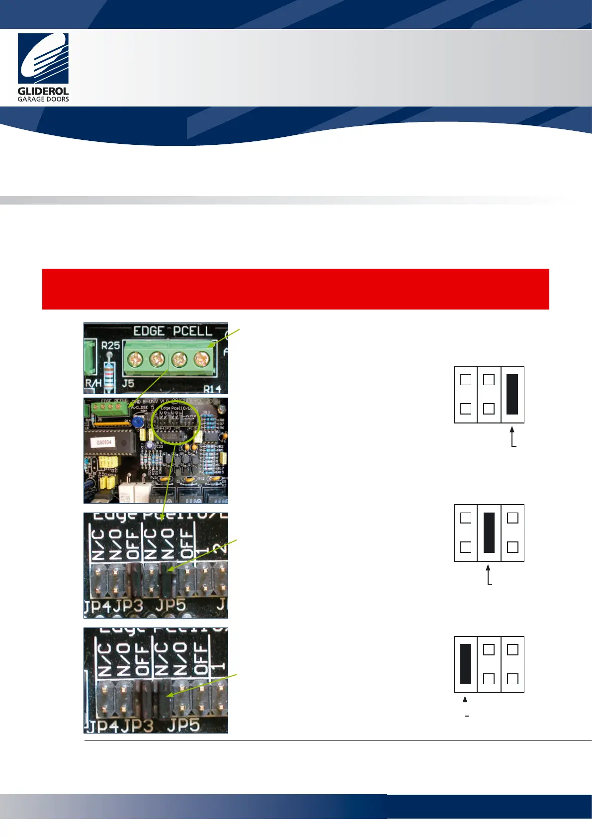
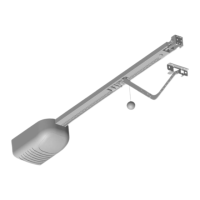
Connect the two wires from the
Photo Electric Cell receiver
output terminals to the terminals
marked PCELL on wiring terminal
J5.
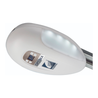
If the Photo Electric Cell
output uses normally open
contacts, move jumper on JP5
from OFF to N/O.
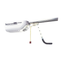
If the Photo Electric Cell
output terminals feature normally
closed contacts, move jumper on
JP5 from OFF to N/C.
N/C
N/O
OFF
MOVE
N/C
N/O
OFF
TO
N/C
N/O
OFF
TO
www.garagedoorsonline.co.uk


 To Next Page