Do you have a question about the Globaljig SYSTEM and is the answer not in the manual?
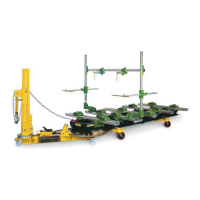
Details the mechanical units and operational aspects of the SYSTEM bench with VECTOR arm.
Provides specific technical specifications, dimensions, and capacities for the VECTOR pulling arm.
Presents a table detailing package codes, descriptions, quantities, and weights for transport.
Outlines procedures for inspecting delivered packages for damage and ensuring integrity upon arrival.
Describes the assembly and substitution of wheels and wheel supports for the SYSTEM bench.
Provides guidance on moving and positioning the SYSTEM bench and VECTOR arm using forklifts or lift trucks.
Details the process of safely removing components from shipping crates and identifying package contents.
Explains the steps for assembling the horizontal and vertical bodies of the VECTOR unit and securing them.
Guides the user through connecting the hydraulic cylinder, male, and female connections for operation.
Details the procedure for inserting and securing the VECTOR unit to the main SYSTEM bench.
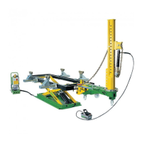
Explains how to use the lever to secure the VECTOR in the optimal position for pulling operations.
Describes the controls for the manual or pneumatic pump that operates the hydraulic cylinder.
Details how to connect the high-resistance steel link chain with a pulling hook to the machine.
Explains how to connect the chain to the body sheet and position the snub pulley for pulling.
Lists crucial safety precautions to follow before and during operational use of the Vector.
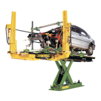
Provides a step-by-step guide on how to perform straightening operations using the SYSTEM bench and VECTOR arm.
Outlines routine checks and cleaning procedures for the VECTOR unit to ensure optimal performance and longevity.
Guides users on troubleshooting hydraulic system breakdowns and contacting authorized service for repairs.
Explains how to obtain mechanical and hydraulic spare parts, emphasizing authorized channels.
Displays a diagram showing the overall dimensions of the VECTOR working arm.
Illustrates the layout and dimensions for the SYSTEM bench's work area and overall footprint.
Provides an exploded view of the VECTOR work arm components, detailing various parts and their identification numbers.
Shows a diagram of the SYSTEM 5m bench, highlighting specific components and their reference codes.
Illustrates the SYSTEM 4m bench, detailing its components and associated part numbers.
Details the different types of bench feet and floor anchoring supports, with associated part identifiers.
Presents various bench wheel configurations and components, including part numbers for identification.
| Brand | Globaljig |
|---|---|
| Model | SYSTEM |
| Category | Lifting Systems |
| Language | English |