Supplied By www.heating spares.co Tel. 0161 620 6677
17
221504A
Diagram 5.14
BOILER MOUNTING
MOUNTING
PLATE
3550
CONTROL
TRAY
FRONT COVER
CASE REMOVAL Diagram 5.13
4810
KEYHOLE SLOT
MOUNTING BRACKET
Diagram 5.12
FOAM SEAL
(Wall Thickness over 300mm)
5 Preparation
Q minus 25mm
Q
FOAM SEAL
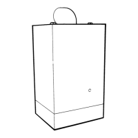
5.12 Boiler Preparation
Remove the controls tray and outer case and place on one side
until required, see diagram 5.13.
Discard packing piece from between front cover and inner case
Note: If convenient, a connection can be made to the gas
service cock at this time.
Lift the boiler into position above the boiler mounting plate,
lowering the boiler into position at the same time locating the
key hole slots of the boiler on to the securing screws, when
located secure the screws, see diagram 5.14.
6897

 Loading...