Operation 8
0020289288_02 MicraCom Installation and maintenance instructions 23
Wiring diagram (→ Page 49)
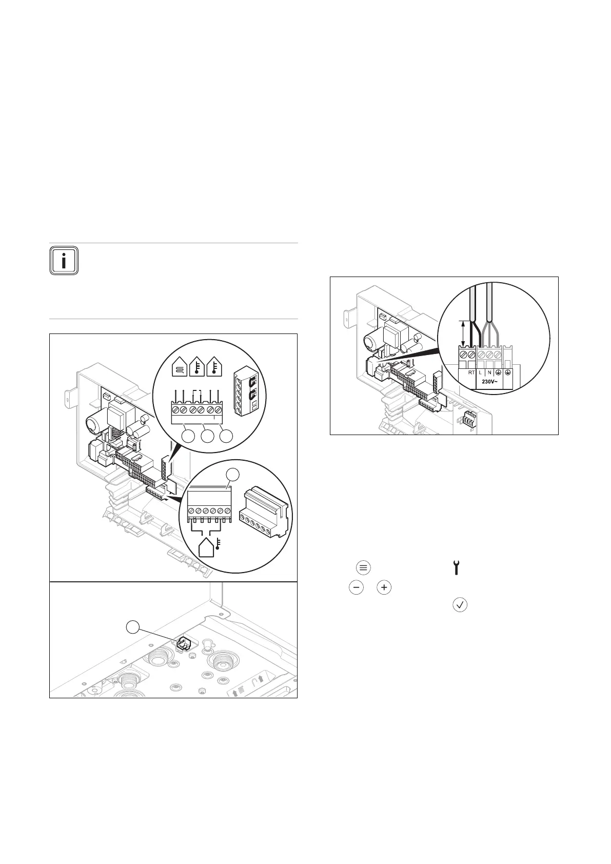
7.9.4 Establishing the power supply
1. Provide one common power supply for the boiler and
for the corresponding control:
– Power supply: Single-phase, 230 V, 50 Hz
– Fuse: ≤ 3 A
2. Ensure that the mains voltage is 230 V.
3. Connect the product using a fixed connection and an
electrical partition with a contact gap of at least 3 mm
(e.g. fuses or power switches).
4. Make sure that access to the power supply is always
available and is not covered or blocked.
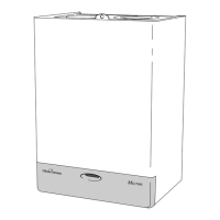
7.9.5 Connecting the control
Note
When connecting to an eBUS room thermostat
after starting up, establish the connection in or-
der to set the heating flow and domestic hot water
temperature on the product to the relevant max-
imum value.
BUS
24V
–
+
24V=
RT BUS
Burner
off
X106
1 Limit thermostat for
underfloor heating
2 Control 24 V (ON/OFF)
3 eBUS control or radio
receiver unit
4 Outdoor temperature
sensor, wired
5 eBUS control or radio
receiver unit
1. Carry out the wiring. (→ Page 22)
2. Alternatives 1 ‒ Connecting the weather-
compensated control or room thermostat via
eBUS:
▶ Connect the control to the BUS connection (3) or
(5).
▶ Bridge the 24 VRT connection, if no bridge is
present.
2.
Alternatives 2 ‒ Connecting the low-voltage
control (24 V):
▶ Remove the bridge and connect the control to the
24 V = RT (2) connection.
2.
Alternatives 3 ‒ Connecting a limit thermostat
for underfloor heating:
▶ Remove the bridge and connect the limit thermostat
to the Burner off (1) connection.
2.
Alternatives 4 ‒ Connecting the 230 V low
voltage room temperature control:
▶ Connect the control to the L main plug and to the RT
plug.
▶ Remove the bridge from the 24V=RT plug.
3. Close the electronics box.
8 Operation
8.1 Calling up the installer level
1. Press repeatedly until the symbol flashes.
2. Use or to set the competent person access
code and confirm by pressing .
– Competent person access code: 35
◁ The d. diagnostics codes menu is displayed.
 Loading...