9 Start-up
26 Installation and maintenance instructions MicraCom 0020289288_02
9.4 Purging the heating installation
1. Start the check programme P.00. (→ Page 24)
Check programmes (→ Page 48)
◁ on is shown in the display.
2. Make sure that the filling pressure of the heating install-
ation does not fall below the minimum filling pressure.
– ≥ 0.05 MPa (≥ 0.50 bar)
3. Check whether the filling pressure of the heating in-
stallation is at least 0.02 MPa (0.2 bar) above the dia-
phragm expansion vessel's counter-pressure (P
system
≥
P
diaphragm expansion vessel
+ 0.02 MPa (0.2 bar)).
Result:
Filling pressure of the heating installation is too low
▶ Refill the heating installation.
4. If there is still too much air in the heating installation at
the end of the check programme P.00, restart the check
programme.
9.5 Filling and purging the domestic hot water
system
1. Open the cold-water isolation valve on the product.
2. To fill the domestic hot water circuit, open all of the do-
mestic hot water tap fittings until water escapes.
9.6 Check and gas setting
9.6.1 Checking the factory-set gas setting
▶ Check the information about the gas type indicated on
the data plate and compare this with the gas type avail-
able at the installation site.
Result 1:
The product design is not compatible with the local gas
group.
▶ Do not start up the product.
▶ Contact customer service.
Result 2:
The product design is compatible with the local gas
group.
▶ Check the gas connection pressure/gas flow pres-
sure. (→ Page 26)
▶ Check the CO₂ content. (→ Page 28)
9.6.2 Checking the air/flue pipe/flue gas
recirculation
1. Check the flue gas installation is intact in accordance
with the latest gas safe technical bulletin and informa-
tion supplied in the installation instructions.
2. For extended flue gas installations check for flue gas
recirculation using the air analysis point.
3. Use a flue gas analyser.
4. If you discover unusual levels of CO or CO
2
in the sup-
ply air, search for the leak in the flue system or for signs
of flue gas recirculation.
5. Eliminate the damage properly.
6. Check again whether the supply air contains any unusal
levels of CO or CO
2
.
7. If you cannot eliminate the damage, do not start up the
product.
9.6.3 Checking the gas flow rate
The boiler is fitted with a multifunctional automatic gas valve
which ensures that the precise air/gas ratio is provided un-
der all operating conditions. The gas flow rate has been set
during production and does not require adjustment. With the
front casing fitted check the gas flow rate of the boiler as fol-
lows:
▶ Start up the product with the check programme P.01.
▶ In addition, ensure that maximum heat can be dissipated
into the heating system by turning up the room thermo-
stat.
▶ Wait at least 5 minutes until the boiler has reached its
operating temperature.
▶ Ensure that all other gas appliances in the property are
turned off.
▶ Measure the gas flow rate at the gas meter.
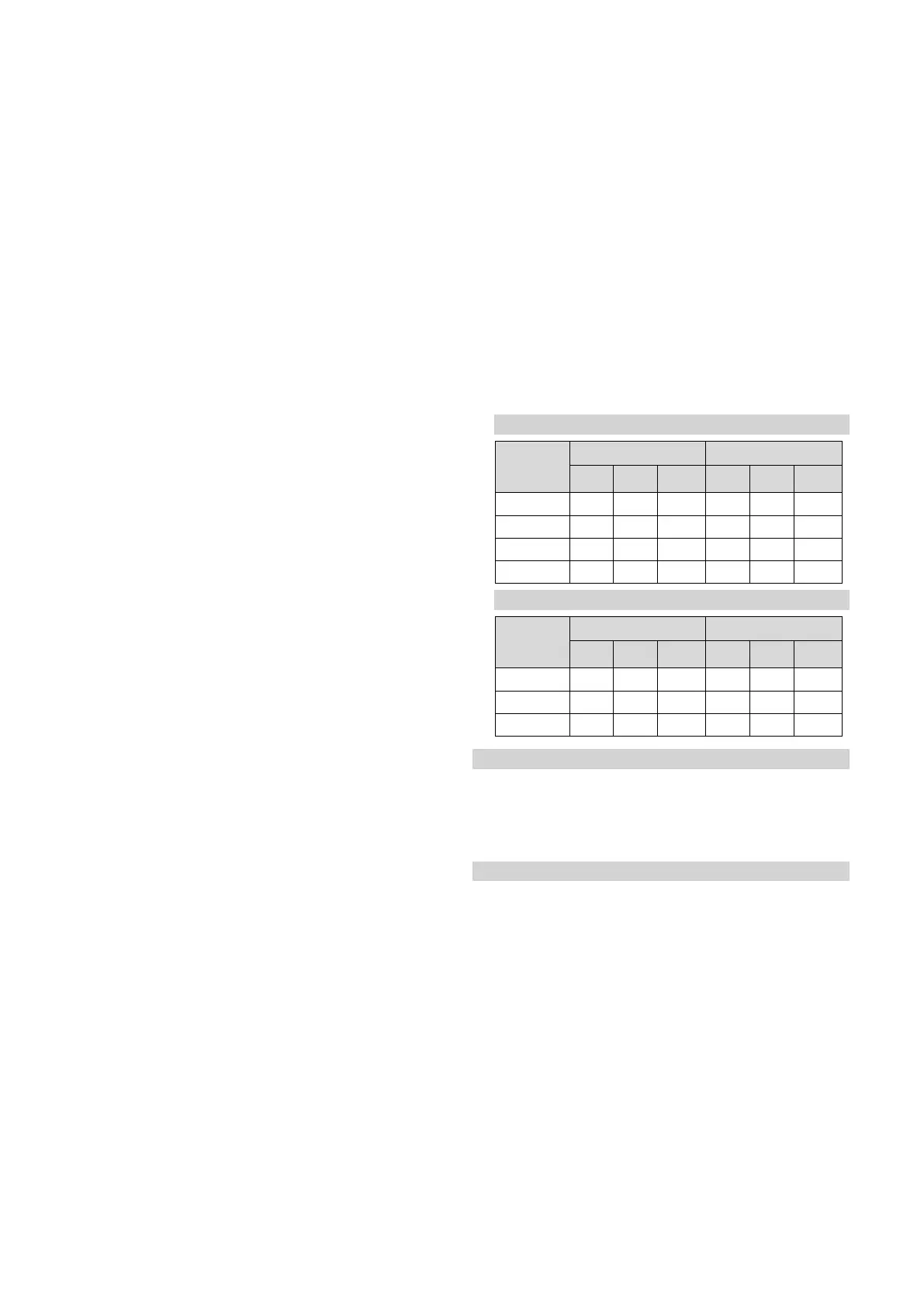
▶ Compare the measured values with the corresponding
values in the table.
Validity: MicraCom 24c-AS/1 (H-GB)
Qnw from
the data
plate
H gas in m³/h P gas in m³/h
Nom.
+5% −10%
Nom.
+5% −10%
6.2 0.65 0.68 0.59 – – –
8.4 – – – 0.34 0.36 0.31
18.8 1.98 2.08 1.78 0.77 0.81 0.69
24 2.53 2.66 2.28 0.98 1.03 0.88
Validity: MicraCom 28c-AS/1 (H-GB)
Qnw from
the data
plate
H gas in m³/h P gas in m³/h
Nom.
+5% −10%
Nom.
+5% −10%
7.2 0.76 0.80 0.68 0.29 0.30 0.26
24.5 2.58 2.71 2.32 1.00 1.05 0.90
28 2.95 3.10 2.66 1.15 1.21 1.04
Condition: Gas flow rate not in the permissible range
▶ Check all of the piping and ensure that the gas flow rates
are correct.
▶ Only put the product into operation once the gas flow
rates have been corrected.
Condition: Gas flow rate in the permissible range
▶ End check programme P.01.
▶ Allow the boiler to cool down by allowing pump overrun to
operate for a minimum of two minutes.
▶ Record the boiler maximum gas flow rate onto the
Benchmark gas boiler commissioning checklist.
9.6.4 Checking the gas connection pressure/gas
flow pressure
1. Temporarily decommission the product. (→ Page 39)
2. Hinge the electronics box downwards.
 Loading...