9 Start-up
28 Installation and maintenance instructions MicraCom 0020289288_02
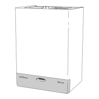
9.6.6 Checking the CO₂ content
1. Open the test opening at the flue gas analysis point (1).
2. Position the sensor for the CO₂ analyser in the centre of
the flue pipe.
3. Start up the product with check programme P.01.
(→ Page 24)
4. Wait at least five minutes until the product reaches its
operating temperature.
5. Measure the CO₂ content at the flue gas analysis point
and log the measured value.
Checking the CO₂ content
Great
Bri-
tain
Fitted front
casing
Natural gas H
9.2 ±1 %
Liquefied petro-
leum gas
P
10.6 ±0.5 %
Result 1:
If the value is outside of the permitted range:
▶ Measure the CO₂ content at the flue gas analysis
point again and log the measured value.
▶ If the value is still outside of the permissible range,
do not start up the product and, instead, report this
to customer service.
Result 2:
If the value is inside the permitted range:
▶
Continue with the process of starting up the product.
6. Remove the sensor for the CO₂ analyser and close the
test opening at the flue gas analysis point.
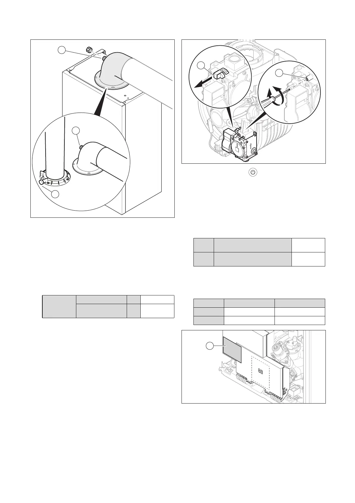
9.6.7 Performing a gas conversion
1. Press the on/off button in order to switch off the
product.
◁ The display shows oF and then goes out.
2. Disconnect the product from the power grid.
3. Remove the plug (1).
4. To convert the gas type, turn the screw (2) by the spe-
cified number of rotations clockwise (↻) or anti-clock-
wise (↺).
Setting the gas valve assembly
H → P Clockwise rotation
Three re-
volutions
P → H Anti-clockwise rotation
Three re-
volutions
5. Check the CO₂ content and adjust this. (→ Page 31)
6. Set diagnostics code d.85 in order to adjust the pro-
duct's minimum output. (→ Page 24)
Setting diagnostics code D.85
24c-AS/1 28c-AS/1
H → P
9 kW 8 kW
P → H
6 kW 7 kW
7. Mark the gas type that is used on the gas conversion
sticker.
8. Stick the gas conversion sticker (1) to the electronics
box.
 Loading...