Start-up 9
0020289288_02 MicraCom Installation and maintenance instructions 27
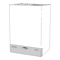
3. Turn the screw on the gas pressure measuring point (1)
anti-clockwise.
– Anti-clockwise (↺): Two rotations
4. Connect a manometer (2) to the test nipple (1).
– Working materials: U tube manometer
– Working materials: Digital pressure gauge
5. Hinge the electronics box upwards.
6. Open the gas stopcock.
7. Start up the product with check programme P.01.
(→ Page 24)
8. Measure the gas connection pressure/gas flow pres-
sure against the atmospheric pressure.
Permissible connection pressure
Great
Bri-
tain
Natural gas H
1.7 to 2.5 kPa
(17.0 to 25.0 mbar)
Liquefied petro-
leum gas
P
2.5 to 4.5 kPa
(25.0 to 45.0 mbar)
Note
The connection pressure is measured at the
gas valve assembly, meaning that the per-
missible minimum value may be 0.1 kPa (1
mbar) lower than the minimum value spe-
cified in the table.
Result 1:
Gas connection pressure/gas flow pressure in the per-
missible range
▶ Temporarily decommission the product. (→ Page 39)
▶ Hinge the electronics box downwards.
▶ Remove the manometer.
▶ Tighten the screw on the test nipple.
▶ Open the gas stopcock.
▶ Check the test nipple for gas tightness.
▶ Hinge the electronics box upwards.
▶ Install the front casing. (→ Page 27)
▶ Start up the product.
Result 2:
Gas connection pressure/gas flow pressure not in the
permissible range
Caution.
Risk of material damage and oper-
ating faults caused by incorrect gas
connection pressure/gas flow pres-
sure.
If the gas connection pressure/gas flow
pressure lies outside the permissible
range, this can cause operating faults
in and damage to the product.
▶ Do not make any adjustments to the
product.
▶ Do not start up the product.
▶ If you are unable to eliminate the fault, contact the
gas supply company.
▶ Close the gas stopcock.
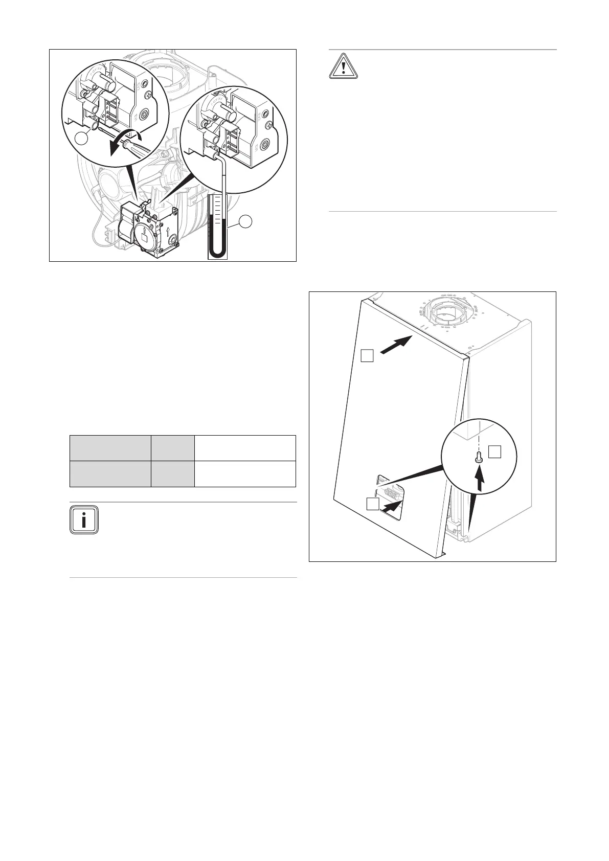
9.6.5 Installing the front casing
 Loading...