Appendix
0020289288_02 MicraCom Installation and maintenance instructions 49
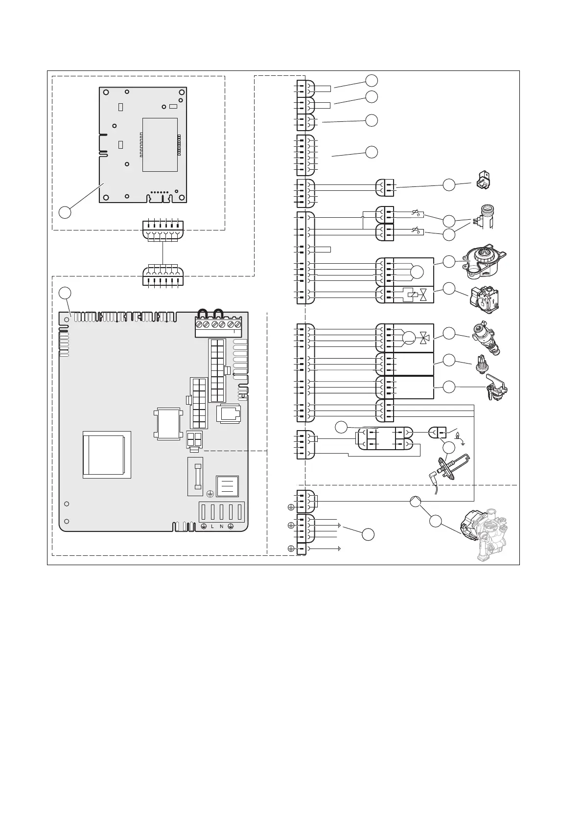
F Wiring diagram
X2
X14
L
N
19
9
20
2
6
3
11
13
14
18
7
17
8
X51
X51
X20
16
1
9
3
15
4
5
10
11
6
13
X51
X20
X40 X51
X30
X2
X21
X41
X22
X14
L
N
–
+
24V=
RT BUS
Burner
off
X1
RT
230Vac
FUS
X106
X32
X90
X12
X35
X1
L
N
RT 230Vac
X21
4
1
3
2
eBUS
RT 24V
Burner off
FB
AF
RF
DCF
0
0
X106
18
17
8
7
10
4
X41
1
3
4
1
3
3
1
2
M
1
3
4
6
1
2
3
M
5
4
2
1
2
1
2
1
N
L
L
24V
230V~
24V
230V~
2
12
13
14
16
1
8
9
10
11
15
1718
17
3
4
5
6
X32
eBUS
1
3
2
4
7
1 Main PCB
2 PCB for the control element
3 Limit thermostat with contact for underfloor heating,
Burner off
(optional)
4 Room thermostat, RT 24 V
(optional)
5 Bus connection for control/room thermostat
(optional)
6 Outdoor temperature sensor, flow temperature
sensor (external), DCF receiver
(optional)
7 External eBUS plug
8 Heating flow temperature sensor
9 Heating return temperature sensor
10 Fan
11 Gas valve assembly
12 Prioritising diverter valve
13 Water pressure sensor
14 Water flow switch
15 Igniter
16 Ignition electrode
17 Pump
18 Main power supply
 Loading...