Installation 7
0020289288_02 MicraCom Installation and maintenance instructions 17
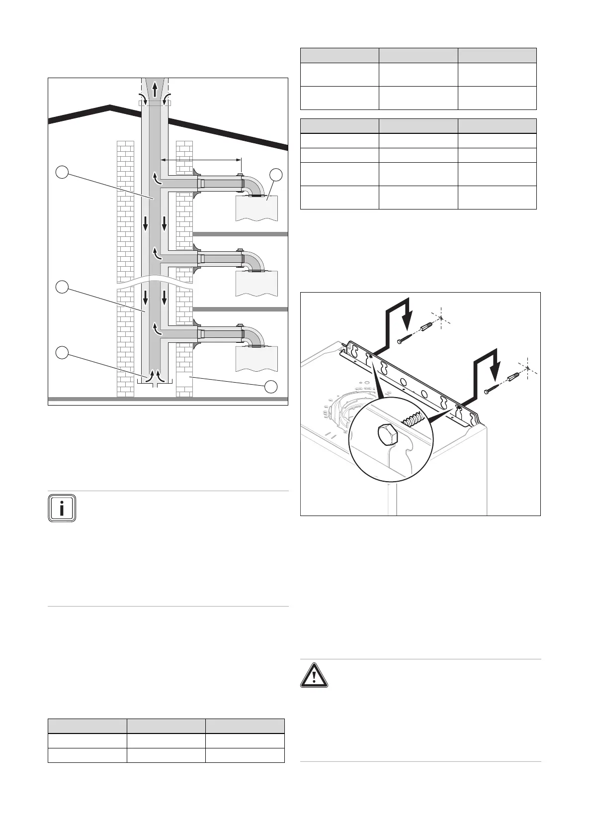
6.5.4.3 Multiple boiler chimney Flue ⌀ 60/100 mm or
⌀ 80/125 mm (C43 type installation)
1 Pressure balancing
system
2 Air-inlet pipe
3 Collector pipe
4 Pressure balancing
system
5 Inspection hatch
A Final storey
B Ground floor
Note
The flue connecting from the appliance to the flue
system must be supplied from the manufacturer of
the boiler.
C43 flue systems must not be a 'pressurised sys-
tem' but act under natural draught principles.
C43 type flue systems must have their own con-
densate drain fitted and not allow condensate to
mix into other appliances.
The flue length must be calculated and installed according
to the relevant standards EN 13384-1 and 2 (C43 flue sys-
tems only) with reference to the table below and the manu-
facturer's instructions supplied. The appliance maximum flue
length must be included when calculating the overall design
of the flue system.
Each time an additional 90° bend is necessary (or 2 at 45°),
the length (L) must be reduced (see table below).
⌀ 60/100 24c-AS/1 28c-AS/1
Min. length (L) 0.3 m 0.3 m
Max. length (L) 3 m + 3 elbow 3 m + 3 elbow
⌀ 60/100 24c-AS/1 28c-AS/1
Equivalence to 1
elbow 90°
1 m 1 m
Equivalence to 1
elbow 45°
0.5 m 0.5 m
⌀ 80/125 24c-AS/1 28c-AS/1
Min. length (L) 0.3 m 0.3 m
Max. length (L) 3 m + 3 elbow 3 m + 3 elbow
Equivalence to 1
elbow 90°
3 m 2.5 m
Equivalence to 1
elbow 45°
1 m 1 m
6.6 Using the mounting template
▶ Use the mounting template to ascertain the locations at
which you need to drill holes and make breakthroughs.
6.7 Wall-mounting the product
1. Check the load-bearing capacity of the wall.
2. Note the total weight of the product. (→ Page 7)
3. Only use fixing material that is permitted for the wall.
– Screws with a minimum diameter of 6 mm
4. If required, ensure that mounting apparatus on-site has
sufficient load-bearing capacity.
5. Wall-mount the product as described.
7 Installation
Danger!
Risk of scalding and/or risk of material
damage due to incorrect installation lead-
ing to escaping water.
Mechanical stresses in connection cables
can cause leaks.
▶ Install the connection cables voltage-free.
 Loading...