ring points to your destination Waypoint relative to your
current track (COG). The compass ring and Bearing Pointer
work independently to show at a glance the direction of your
movement and direction to your destination.
e.g. if the Bearing Pointer points Up you are travelling directly
towards your destination. If the Bearing Pointer points in any
other direction you must turn towards the pointer until it points
Up in order to continue towards your destination.
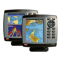
POSITIONAL NAVIGATION DATA DISPLAY
The positional navigation data display provides GPS status,
position in Latitude and Longitude, course over ground, speed
over ground and the time and date. This page is useful for
determining your current location for relaying to others or for
simply confirming the current time or date.
USER CONFIGURABLE NAVIGATION DISPLAYS
There are two User Configurable Navigation displays that
can be set either as ‘Big Number’ navigation fields or as an
analogue Speedometer.
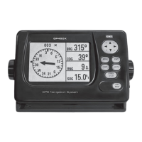
Big Number Navigation Display
The ‘Big Number’ Navigation display is used to show digital
navigation information. It can be configured into 1, 2, 3 or 4
separate fields on the screen as shown below.
Each field can be individually configured to display
• Time
• Speed over Ground (SOG),
• Cross Track error (XTE)
• Odometer Distance
• Position
• Course over Ground (COG)
• Time to Go (to Destination) (TTG)
• Trip Distance
• External Voltage (Volts)
• Range and Bearing to Waypoint
• Estimated time of Arrival (ETA)
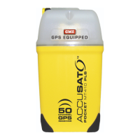
SPEEDOMETER DISPLAY
The Speedometer displays Speed over Ground. The display
can be configured to suit the speed limitations of your vessel
or the speed range of a specific application (such as trolling).
The Speedometer has 5 interval calibrations from minimum
to maximum. Simply set the minimum speed and the interval
speed and the Speedometer will be calibrated automatically.
The example above shows the minimum speed set to 0 knots
with the intervals set to 10 knots resulting in a Speedometer
calibrated from 0 to 40 knots with 10 knot intervals.
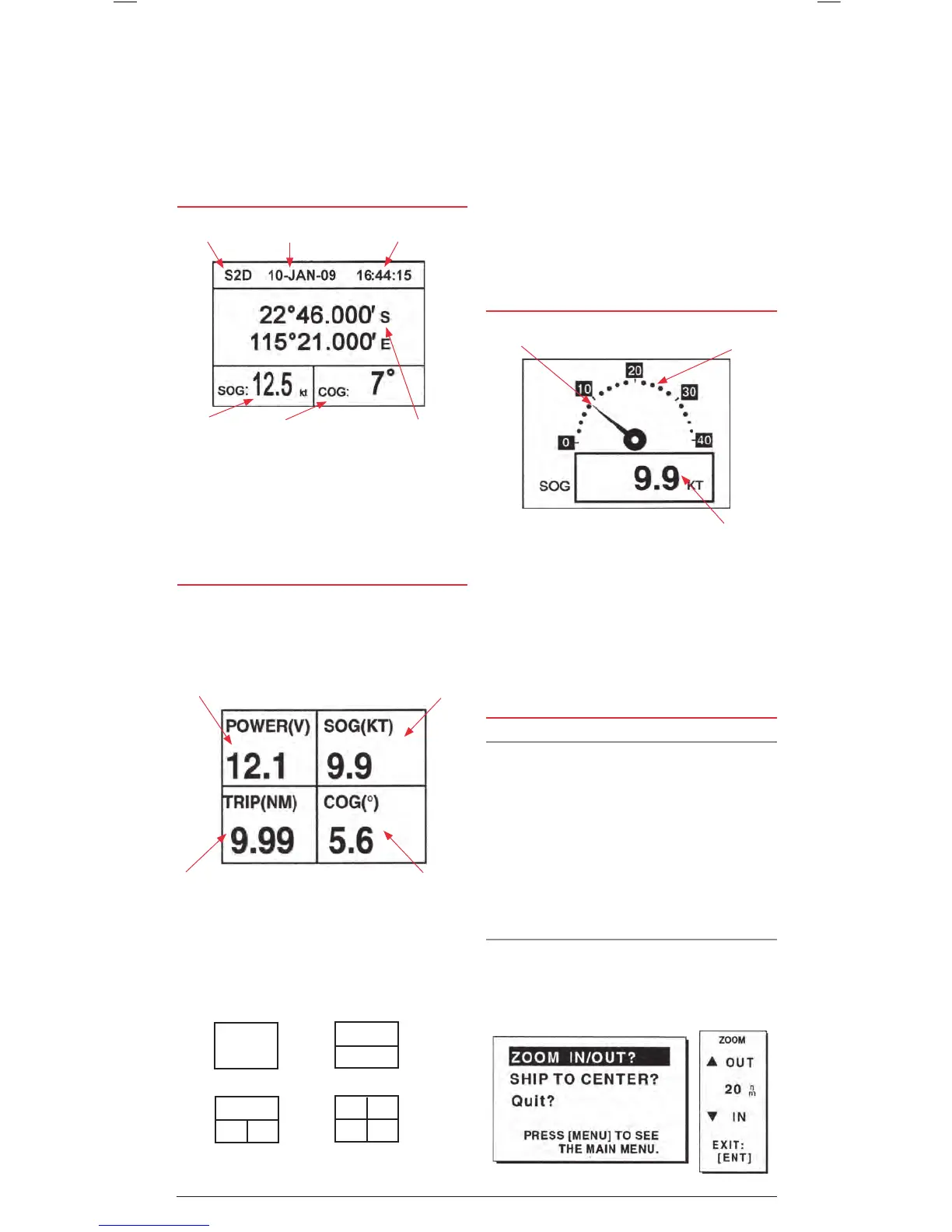
CONTROLLING THE PLOTTER DISPLAY
Display Range
You can select the display range (Zoom Level) on both the
plotter and highway displays.
On the plotter screen the horizontal display range is shown in
the lower left corner of the display. The range of the plotter
display can be set from 0.02 to 320 display units. The display
units can be preset to nautical miles, kilometres or statute miles.
For maximum display range set the units to nautical miles to
provide a maximum range of 320 nm.
On the highway screen the zoom range can be set from 0.2 to
16 display units.
Selecting the Display range
With the plotter or highway window selected;
1. Press the MENU key. The ZOOM, SHIP TO CENTRE menu
appears and ZOOM IN/OUT is highlighted.
One Field
Two Fields
Three Fields Four Fields
Speed Pointer
Analogue Speed dial
Digital Speed
Receiver Status
Speed over
ground.
Course over
Ground.
Position in Latitude
and Longitude.
TimeDate
Field 1
e.g. External Voltage
Field 4
e.g. Course over
Ground.
Field 3
e.g. Trip Meter
Field 2
e.g. Speed over Ground.
 Loading...