15
Fury X-3 Installaon and Operang Instrucons
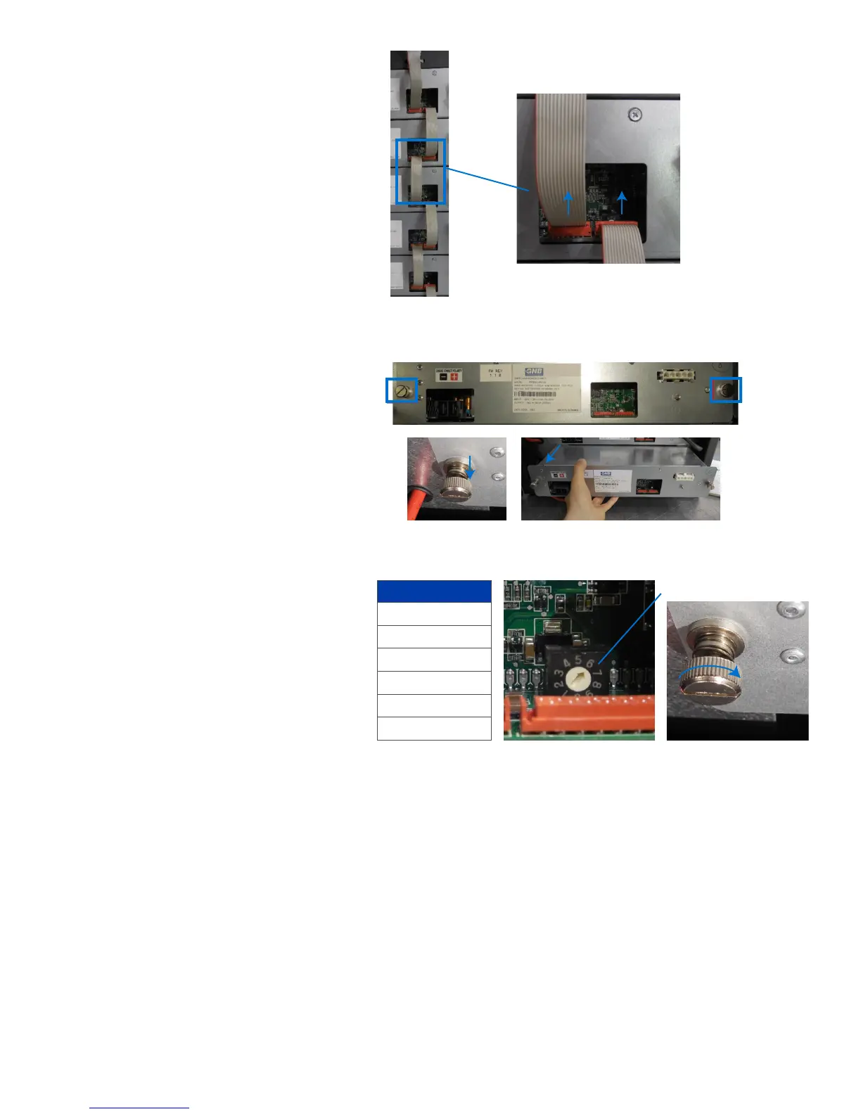
Mul-Cable Connecon
For a mul-cable connecon, you only need to disconnect the
communicaon cables from the module you are replacing.
Step 4. Loosen Mounng Screws and Remove
Power Module
Using a at head screwdriver, turn each mounng screw
counter clockwise unl the spring ejects and releases the
screw from the nut. Carefully pull the power module out.
Step 5. Insert Replacement Module and Set Module
Posion Selector
Insert the replacement power module. Use a at head screw
driver to ghten the mounng screws by pushing in and
turning clock-wise.
Using a at head screw driver, adjust the module posion
selector to match the modules posion. The power module
posions are 1 through 6 starng at the top of the charger as
shown in the following table:
Step 6. Reconnect Communicaon and Power Cables
Reconnect all communicaon cables that were disconnected in step 3. Reconnect ground , DC output, and AC input cables. Close charger
door and use at head screw driver to turn the latch counter-clockwise to lock.
Charger
Module 1
Module 2
Module 3
Module 4
Module 5
Module 6
Power Module
Posion Selector


 To Next Page