3636 3737
Settings / Sensors / Sensors Configu-
ration / Current Sensors
If you select one of the internals I1 to I6 (loads)
in the "Sensors" view, you will get to the data
overview of the respective sensor/internal. In
the settings directly on the Controller, a similar
view can be found under the "Load settings".
Here you can invert a load via the slider, if you
have not connected a current transformer with
the arrows in current direction. Note that the
power should always be positive when drawing
from the grid. For a solar inverter or AC battery,
the power should be positive when feeding. Ho-
wever, if the battery is being charged or the in-
verter has a higher standby consumption than
it generates, the power may be negative. If no
power is being consumed, the power should be
close to 0.
If you want to adjust an assigned load catego-
ry or change the phase assignment, this is also
possible here in the overview of the respective
current sensor. This works similar to the menu
of the go-e Controller itself.
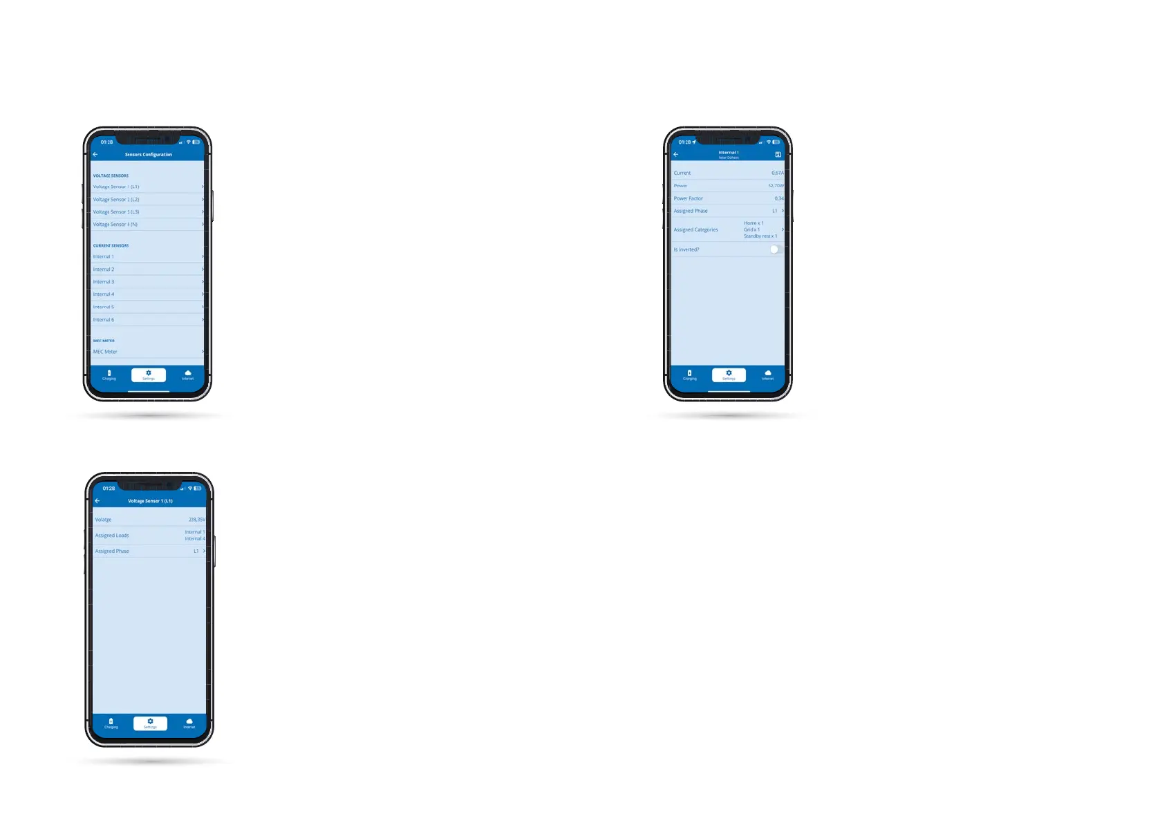
10b. Commissioning/operation via app
As on the Controller itself, you can congure
the voltage and current sensors in the menu
item "Settings", submenu "Sensors" and read
their voltages, currents and powers in real time
after selecting them. You can also do this direct-
ly on the go-e Controller.
Voltage sensors L1 to L3 always measure the
voltage of the connected phases and current
sensors Internal 1 to Internal 6 measure the
current and power. To ensure that the power
calculation by the go-e Controller is really cor-
rect and that functionalities such as PV surplus
charging and dynamic load balancing work pro-
perly, you need to make sure that you have set
the correct voltage reference for all phases and
that the correct categories and power factors
are stored. What exactly has to be observed is
explained in this manual in chapter "10a. Com-
missioning/operation on the device" using vari-
ous examples. Below, we will only explain whe-
re you can nd which settings in the app.
Settings / Sensors / Sen-
sors Configuration
If you select one of the voltage sensors, e.g. vol-
tage sensor L1, you will see all measured values
of the selected phase.
If you have connected one or more phases of
the power supply incorrectly, you could also
change the voltage phase assignments here by
pressing "Assigned Phase".
Settings / Sensors / Sensors Configu-
ration / Voltage Sensors