gpelectric.com | [page 11]
After completion of the set-up wizard, set the proper shunt current and shunt voltage according to Section 4.2.5,
setting number 65 and 66.
If the GP-BMK-50 reads a non-zero current, even when there is no load and the battery is not being charged, calibrate
the zero current reading (see section 4.2.1, setting number 09).
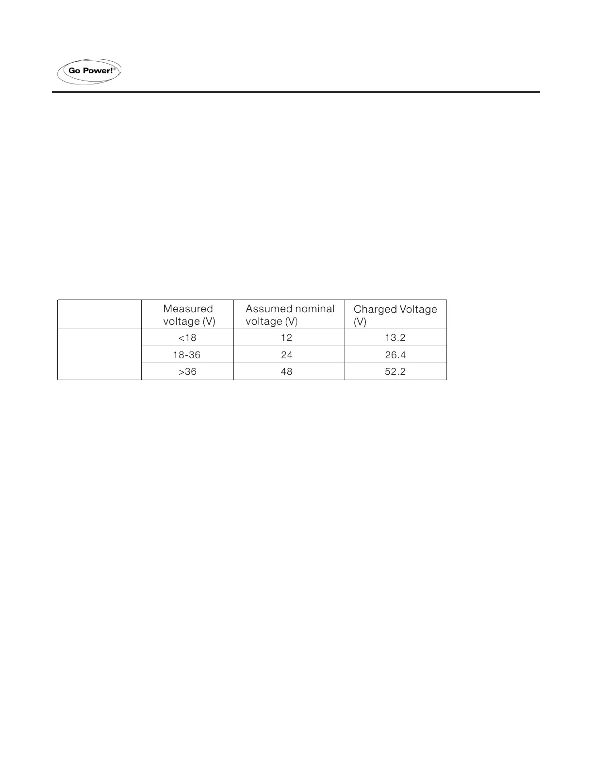
4.6 AUTOMATIC DETECTION OF NOMINAL SYSTEM VOLTAGE
The GP-BMK-50 will automatically adjust itself to the nominal voltage of the battery bank, immediately after completion
of the set-up wizard.
The following table shows how the nominal voltage is determined and how the charged voltage parameter (see
section 2.2) is adjected as a result.
In case of another nominal battery bank voltage (32V for example), the Charged Voltage must be set manually
(see section 4.2.1, setting 02).
Recommended Settings
(Nominal Battery Voltage)
Recommended Charged
Voltage Setting
12V 13.2V
24V 26.4V
36V 39.6V
48V 52.8V
60V 66V
120V 132V
144V 158.4V
288V 316.8V
4.7 ALARM, BUZZER AND RELAY
On most of the GP-BMK-50’s readings, an alarm can be triggered when the value reaches a set threshold. When
the alarm becomes active the buzzer starts to beep, the back-light ashes and the alarm icon is visible in the display
along with the current value.
The corresponding segment will also ash. AUX when a starter alarm occurs. MAIN, MID or TEMP for the corresponding
alarm.
(When in the set-up menu and an alarm occurs, the value causing the alarm will not be visible.)
An alarm is acknowledged when a button is pressed. However, the alarm icon is displayed as long as the alarm
condition remains.
FEATURES AND FUNCTIONALITY
GP-BMK
GP-BMK-50
 Loading...