gpelectric.com | [page 13]
4.9.3 MIDPOINT VOLTAGE MONITORING
Wiring diagram: see the quick installation guide. Fig 5 - 12
One bad cell or one bad battery can destroy a large, expensive battery bank. A short circuit or high internal leakage
current in one cell for example will result in under charge of that cell and over charge of the other cells.
Similarly, one bad battery in a 24Vor 48V bank of several series/parallel connected 12V batteries can destroy the
whole bank.
Moreover, when cells or batteries are connected in series, they should all have the same initial state-of-charge. Small
dierences will be ironed out during absorption or equalize charging, but large dierences will result in damage during
charging due to excessive gassing of the cells or batteries with the highest initial state-of-charge.
A timely alarm can be generated by monitoring the midpoint of the battery bank. For more information, see section 5.1.
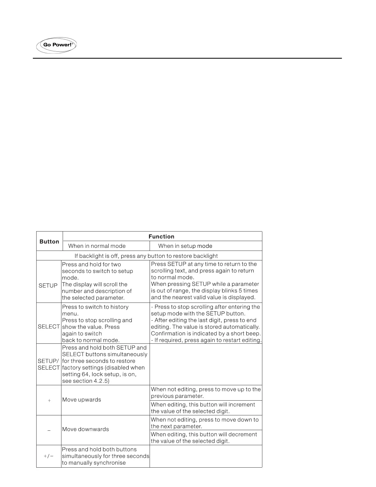
5.1 USING THE MENUS
Four buttons control the GP-BMK-50. The function of the buttons depends on which mode the GP-BMK-50 is in.
5. FULL SET-UP DETAILS
 Loading...