[page 8] | gpelectric.com
NORMAL OPERATING MODE
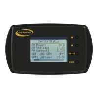
BATTERY BANK TOP SECTION VOLTAGE:
When the auxiliary input set to MID. Compare with the bottom
section voltage to check battery balancing. For more about battery
midpoint monitoring, see section 5.2.
BATTERY BANK BOTTOM SECTION VOLTAGE:
When the auxiliary input is set to MID. Compare with the top section
voltage to check battery balancing.
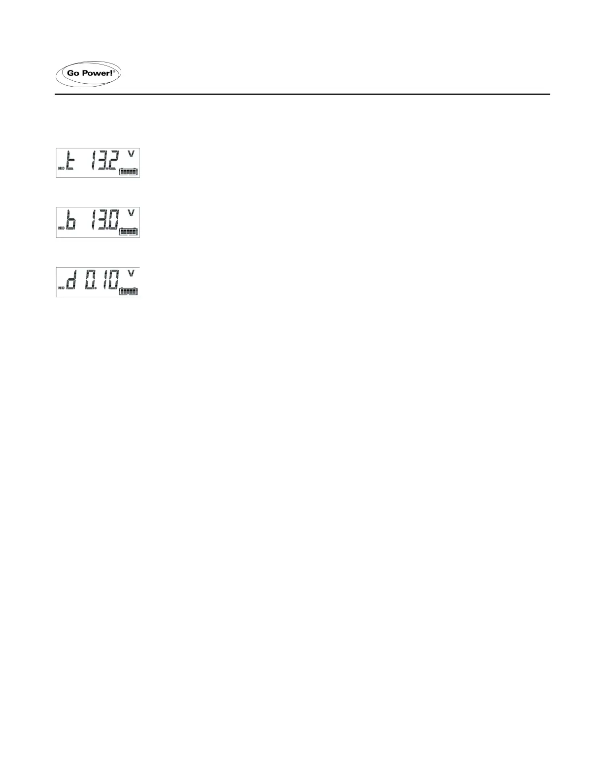
BATTERY BANK MID-POINT DEVIATION VOLTAGE:
When the auxiliary input is set to MID. Deviation in Volts of the
mid-point voltage.
3.2 SYNCHRONIZING THE GP-BMK-50
For a reliable readout, the state of charge as displayed by the battery monitor has to be synchronized regularly with
the true state of charge of the battery. This is accomplished by fully charging the battery.
In case of a 12V battery, the GP-BMK resets to ‘fully charged’ when the following ‘charged parameters’ are met: the
voltage exceeds 13.2V and simultaneously the (tail-) charge current is less than 4.0% of the total battery capacity
(e.g. 8A for a 200Ah battery) during 4 minutes.
The GP-BMK can also be synchronized (i.e. set to ‘battery fully charged’) manually if required. This can be achieved
in normal operating mode by holding the + and – buttons simultaneously for 3 seconds, or in setup mode by using
the SYNC option (see section 4.2.1, setting number 10).
If the GP-BMK does not synchronize automatically, the charged voltage, tail current, and/or charged time may need
adjustment.
When the voltage supply to the BMK has been interrupted, the battery monitor must be resynchronized before it
can operate correctly.
3.3 COMMON PROBLEMS
NO SIGNS OF LIFE ON THE DISPLAY
Probably the GP-BMK-50 is not properly wired. The UTP cable should be properly inserted at both ends, the shunts
must be connected to the minus pole of the battery and the positive supply cable should be connected to the plus
pole of the battery with the fuse inserted.
The temperature sensor (when used) must be connected to the positive pole of the battery bank (one of the two
wires for the sensor doubles as the power supply wire).
CHARGE AND DISCHARGE CURRENT ARE INVERTED
Charge current should be shown as a positive value. For example: +1.45A.
Discharge current should be shown as a negative value. For example: -1.45A.
If charge and discharge current are inverted, the power cables on the shunt must be swapped: see the quick
installation guide.

 Loading...