BlueSense Module
GO Systemelektronik GmbH Faluner Weg 1 24109 Kiel Germany Tel.: +49 431 58080-0 Fax: -58080-11
Page 11 / 16
www.go-sys.de info@go-sys.de
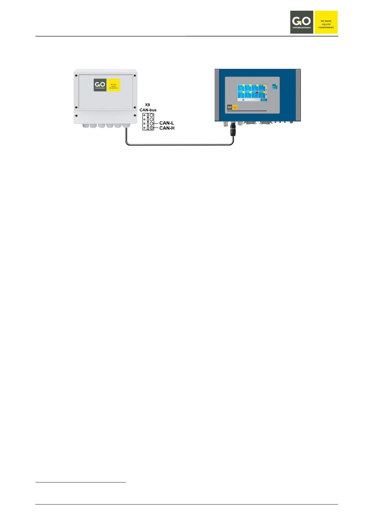
4 Connection to a BlueBox
Connect the cable with CAN-H and CAN-L at the BlueSense Module (see connection diagram page 6 or 7). Con-
nect the BlueBox with a fitting M12-connector.
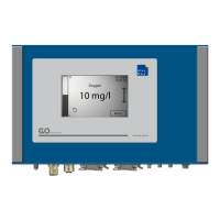
The BlueBox identifies the BlueSense Module automatically and displays the measurement and input values.
The serial number of the BlueSense Module (bbm + 5 digits) is also the CAN-ID
1
of the BlueSense Module for a
connected BlueBox.
Sensor-ID = CAN-ID
1
+ Sensor number
Sensor numbers of the BlueSense Module in order:
• max. 4 connected sensors
• 2 pulse inputs
• 2 digital Inputs
• 2 current outputs
2
• 4 relay outputs
Depending on the number of connected sensors the Sensor numbers of the following sensors respectively
inputs and outputs increase or decrease.
1
In other contexts also called DAM-ID.
2
The current outputs are optional.