BlueSense Module
GO Systemelektronik GmbH Faluner Weg 1 24109 Kiel Germany Tel.: +49 431 58080-0 Fax: -58080-11
Page 5 / 16
www.go-sys.de info@go-sys.de
2 Technical Data and Connection Diagrams
2.1 Technical Data
Article-Nr. 485 0001–X
Inputs:
• 1 or 2 analogue inputs (1 Control parameter or 2 Control parameters)
The particular configuration is on the shipping note, the serial number
of the BlueSense Module is written on the type plate at the right hand
side of the housing.
• 2 pulse inputs, selectable to PNP/NPN (also statically usable),
switching current approx. 6 mA,
measurement range 0.05 Hz – 1000 Hz
• 2 digital inputs (static), potential-free contacts, switching current approx. 6 mA
Outputs:
• 2 current outputs
1
(4 to 20 mA), active
• 2 relays with a low-voltage (only) switching capacity of 24 V / 0.5 A
• 2 relays with a switching capacity of 230 VAC / 2 A or 24 VDC / 6 A
Interfaces:
• CAN-bus connector for connection to the BlueBox System, 50 Kbit/s
Voltage feed:
2
• 12 VDC (9 – 18 VDC), received power max. 15 W
or
• 24 VDC (18 – 36 VDC), received power max. 15 W
or
• 230 VAC (90 – 260 VAC), received power max. 15 W
Housing: Polycarbonate, 235 mm x 185 mm x 119 mm; protection code IP65;
Weight: approx. 1.2 kg
Ambient temperature: -10 °C to +45 °C
1
The current outputs are optional.
2
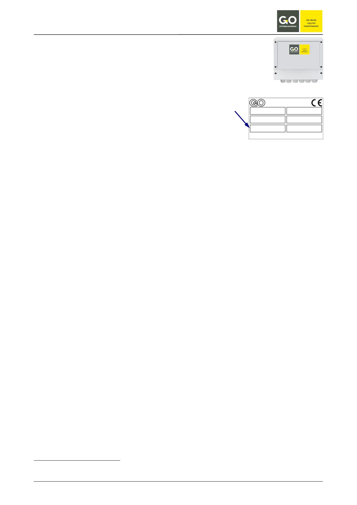
The type of your BlueSense Module is documented on the label on the inside of the cover lid of the cable connections.
G O S y s te m ele k tr o n ik G m b H
G O S y s te m e le ktr o nik G m b H 24 1 0 8 K ie l Te l. : 0 43 1 / 5 80 80 0
F a x 5 8 0 80 11 Em a i l : b lu eb o x @ g o -s ys . d e In te r n e t: w w w. g o - s ys . d e
Ty p e : M e s s u m f o r m e r
A n s c h lu s s w e r t e :
A rt. N r. : 4 8 6 M 0 0
2 3 0 V
S N : 1 2 3 4 1 5 / 1 8