SmartBox
®
4 / SmartBox
®
4 PRO
part no. 28 400 57 d 7 / 28
Connection of relay contacts at the indicator SmartBox
®
4
The Indicator SmartBox
®
4 has two relay contact pairs for the connection of external control
circuits or for activating external alarm or signal devices.
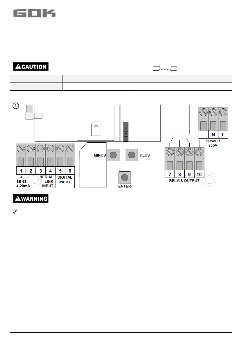
In case of failure of the unit and if the fill level (and optionally temperature) is above / below
the selected limit, the contacts of relay terminals 7 + 8 are closed, or 9 + 10 are open - see
the legend on the PCB in the unit.
Switching voltage max. 250 V AC
Switching current max. 3,5 A
SmartBox
®
4
Excess voltage!
Damage to components and device defect.
No 230 V AC connections may be made to terminals 3 + 4 and 5 + 6 or probe input
terminals 1 + 2!
Connetion of the interface SmartBox
®
4 to SmartBox
®
1, 2 or 3
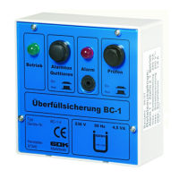
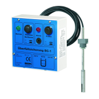
Via the integrated interface “SERIAL LINK INPUT“ (terminals 3 + 4), a maximum of three
additional indicators SmartBox
®
1, 2 or 3 can be connected and the measured values for the
additional tanks (tank 2 to tank 4) can be telecommunicated.
For SmartBox
®
1 and 2, the two-pole output terminal “Serial Link Output“ (terminals 3 + 4) is
con-nected to terminals 3 + 4 (terminal 3 3 and 4 4) of the SmartBox
®
4 with a two-core
cable (e. g. 2 x 0.4 mm²).
If the tanks should be numbered in a defined sequence (tank 2 to 4), then SmartBox
®
4 must
be activated first, followed by the other indicators in the desired sequence.
SIM-