SmartBox
®
4 / SmartBox
®
4 PRO
8 / 28 part no. 28 400 57 d
SmartBox
®
4 PRO
Excess voltage!
Damage to components and device defect.
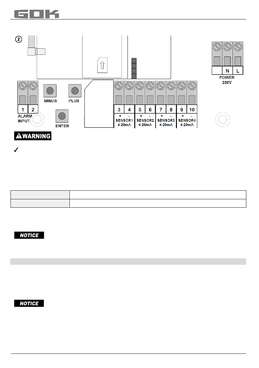
No 230 V AC connections may be made to terminals 3 + 4, 5 + 6, 7 + 8 and 9 + 10 or
terminals 1 + 2 „ALARM INPUT“!
Connection of the fault signal input
A switch contact (make or break contact) can be connected to the fault message input; for a
burner fault signal, for example. If a fault occurs, an SMS text is sent to the administrator's
mobile phone (with an approx. 5-minute delay).
SmartBox
®
4
Terminal 5 + 6 “DIGITAL INPUT“
SmartBox
®
4 PRO
Terminal 1 + 2 “ALARM INPUT“
Installation of the SIM card
A Nano-SIM card must be inserted into the GSM radio module (works with prepaid or contract
card).
The SIM card must have been registered i.e. activated!
The credit on a prepaid card can be topped up again. When a contract card is used, the
transmission fees for the SMS are debited to the holder of the contract.
START-UP
Operation elements and display
The device is adjusted once when it is put into operation. After start-up the device operates in
display mode with the top closed.
The display is a two-line LCD display with 2 x 16 characters.
The display has blue background lighting for best readability in all lighting conditions.
After the level indicator has been installed, it can be started up.
Before activating power supply, check whether the SIM card is correctly inserted in the radio
module! (The SIM card must be fully inserted and locked in place).
Nano
SIM-