Commander III
2-15
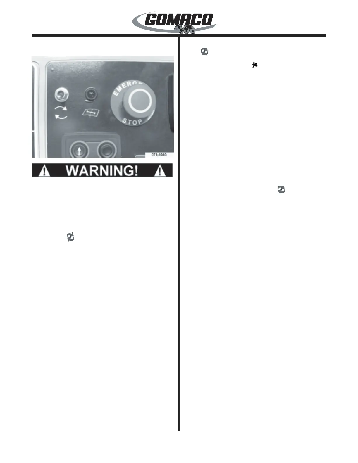
06―G+ Control Panel
071-1010
0044
A defective emergency stop system may cause
severe injury or death. Do not operate the
machine with an inoperative emergency stop
system. Check the emergency stop system daily
for proper working order before beginning paving
operations.
Fault Reset ( ) Switch: Used to reset the controller
when a fault has been detected. The reset switch
should be activated (moved upward and released)
whenever the fault/standby indicator lamp is
illuminated. If the lamp is ashing, refer to the fault/
standby indicator lamp explanation below.
Emergency stop switches must be reset and all faults
must be removed prior to activating the fault reset
switch. The controller will distinguish faults as minor
or critical faults. Minor faults require the repair of the
fault, pushing the fault reset switch to remove the
active fault and pressing the run/standby switch to
resume pouring operations at the previous settings.
Critical faults require all potentiometers and direction
switches be returned to the “off” or “neutral” position
before resetting the controller. Refer to the controller
active fault display for more information.
Note: Placing a faulted control loop in manual
(M) may allow manual operation of the system
depending upon the type of fault detected.
Fault/Standby Indicator Lamp: Used to indicate
when a fault occurs in the control system or when the
controller is in “standby” mode. If a fault is detected,
the lamp will remain illuminated and the controller
will stop all machine functions. If the controller is in
“standby” mode, the lamp will ash. Activate the fault
reset ( ) switch to reset the system. If all faults have
been corrected, the lamp will ash. The ashing lamp
will go out when the Run ( ) switch is depressed.
Note: The fault/standby indicator lamp will be
illuminated after initial start up of the engine as
well as whenever an emergency stop switch has
been depressed.
Emergency Stop Switch: Used to stop all functions
on the machine. Emergency stop switches are located
on the control console and on each elevation leg (two
emergency stop buttons are possible on each leg).
The switches must all be pulled out to operate the
machine. If any switch is depressed, the machine
travel, trimmer, auger/conveyor, vibrators and lift
circuits will be deactivated. Refer to the active fault
display (see later) to determine which E-stop switch is
at fault (depressed). After the emergency stop switch
is pulled out (reset), it will be necessary to reset the
system by activating the fault reset ( ) switch. Make
certain all controls are in the "off" or "neutral" position
before resetting the emergency stop system. To
resume travel in either direction, place the controller
in the "run" mode, depress the desired travel direction
switch and rotate the travel variable control dial to the
desired setting.
Note: All emergency stop switches must be pulled
out to operate the machine. The operation of the
emergency stop system must be checked every
day before beginning operation.
 Loading...