Commander III
2-18
setting. The conveyor will remain in operation to allow
lling of the form hopper.
Note: The vibrators will not operate when the
reverse travel direction is selected.
220-0010
Run/standby switch: Press the switch to select the
run or standby operating mode for the controller.
The mode selection is shown in the center section of
the Run Menu (see run menu description later). All
automatic signals to the control valves are turned off
and the fault/standby indicator lamp will ash when
standby mode is selected.
The controller must be in run mode to operate the
travel, trimmer, auger/conveyor or vibrator systems.
The individual control loops must be in automatic
mode to control the signal to the corresponding control
valve.
W238
Severe injury or death could result if personnel are
caught in moving machine parts. Be certain the
area in front of, and behind the machine is clear
before moving the machine. Be certain the tracks,
trimmer and auger/conveyor are clear before
engaging the controls.
The operator may use the run/standby switch to
stop and resume paving operations. All controls
will be placed in standby mode to stop operation.
The machine controls will resume operation at their
previous settings when the controller is returned to the
run mode.
Track Two Speed Switch: Press the switch to select
the high or low travel mode for the track drive motors.
Stop the machine. The low ( ) mode will shift the
motors into high torque/low speed and high ( ) mode
is low torque/high speed. The low speed range for a
3-track machine is 0 to 49.0 fpm (0 to 15.0 mpm) and
up to 125 fpm (38 mpm) in high speed range. The low
speed range for a 4-track machine is 0 to 37.0 fpm (0
to 11 mpm) and up to 94 fpm (29 mpm) in high speed
range. The speed mode will be displayed on the Run
menu (see run menu description later). The low speed
range must be used during pouring operations. The
vibrators will not operate when high speed range is
selected.
Variable Speed Control Dial: Controls the speed
of machine travel in forward or reverse. The dial can
also be used to start and stop the machine travel.
Stop the machine by rotating the dial counterclockwise
until 0% travel speed is indicated on the Run Menu.
Rotating the dial in the increase direction (clockwise)
will start the machine travel in the desired direction
and will increase travel speed if the machine is already
moving. Rotating the dial in the decrease direction
(counterclockwise) will reduce the travel speed and will
stop the machine at 0% travel speed.
Starting and stopping of the vibrators is also controlled
by the variable speed control dial. The vibrators will
stop operating below 5% and will begin operation
above 5% travel speed. The travel speed percentage
(%) is shown on the bottom center of the Run Menu
(see run menu description later). Press the center
switch on the dial to return the travel speed to 0%
and cause the vibrator and travel systems to stop
operation.
Note: The hydraulic vibrator variable control
valves must be turned in the "increase" direction to
operate the corresponding vibrators.
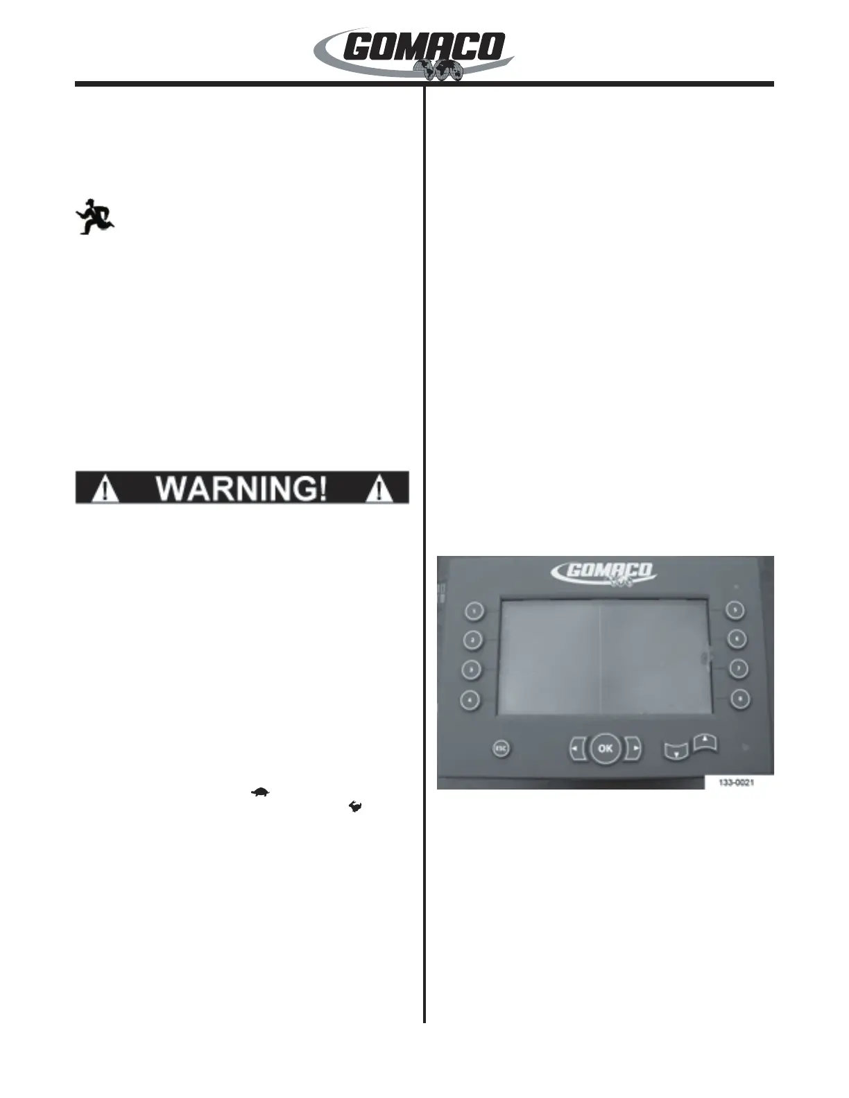
07–G+ Display
133-0021
G+ Display Faceplate switches and buttons:
Warning LED lamp: The warning LED lamp (lower
right corner) will indicate red if an emergency stop
switch is pressed or if there is a fault in the controller
or the sensors. If the controller is in standby, the
light ashes on and off. If there are no faults in the
controller or sensors, and the controller is in run, the
light will indicate green.
Navigation buttons: The up (▲), down (▼), right
(►), or left (◄) buttons are used to move the red
selection cursor on the display screen to a desired
menu item. The up (▲) or down (▼) buttons are also
 Loading...