Commander III
2-20
a grade sensor moves up or down, a bar appears in
the top or bottom half of the indicator.
The bar will change in color from green, to yellow, to
red as the signal strength increases and will change
from red to yellow to green as the signal strength
decreases. The deviation signal has a numerical
value from "0" (centered) to "±1000" (maximum
strength) that can be viewed or hidden by pressing
the ◄ navigation button. The green bar will appear
for a signal strength from "0" to "125". The grade
sensor wand movement will be from centered, to
approximately 0.375 in. (10 mm). The yellow bar
will appear for a signal strength from "126" to "400".
The grade sensor wand movement will be from 0.375
in (10 mm) to approximately 2.0 in (50 mm). The
red bar will appear for a signal strength in excess of
"401". The grade sensor wand movement will be in
excess of 2.0 in (50 mm) (may cause "off stringline"
to be displayed). If there is no error signal, the bar
disappears (centers). The steering deviation signals
will be similar to the grade.
The deviation numerical values for the smart cylinders
are shown over the steer deviation meters. The
rectangular indicator that is centered between all the
deviation meters will show the steer sensor deviation
on the appropriate side.
Note: The (~) mark shown in the left front
elevation indicator appears when the bump lter
(see later in the setup menu) has been activated
and a bump has been detected.
The automatic or manual control mode of each
individual control loop is indicated by the letter “M”
(manual) or the letter “A” (automatic) next to the
corresponding display. If the control loop is in manual,
the letter “M” will be illuminated next to the indicator
(the indicator rectangle turns red when the control loop
is in manual). In the manual mode, the corresponding
system will respond to the jog switches. If the control
loop is in automatic, the letter “A” will be illuminated
above the indicator (the indicator rectangle turns green
when the control loop is in automatic). In automatic,
the corresponding system will respond to signals from
the sensor. The jog switches will override the sensor
signals when the control loop is in the automatic mode.
Press the appropriate A/M switch to change between
automatic and manual.
Slope setpoint section: The slope setpoint section
in the upper right corner of the menu monitors the
cross slope of the machine frame. Press the number
5 button to select the cross slope percentage. Press
the ▲ or ▼ navigation buttons to change the slope
setting in 0.05% increments. Press and hold the ▲ or
▼ navigation buttons to rapidly change the cross slope
percentage. Adjustment range is from 0.00 to 9.50%
in either direction. A red cursor will indicate selection
of the slope percentage and will disappear after 2 to 3
seconds of inactivity.
The percent of slope is shown at the bottom of the
slope set point section. The direction of slope is
indicated by a wedge that will appear when the slope
is changed either direction from 0.0%. If the machine
frame is commanded to tilt to the left, the wedge
symbol will appear, tilted to the left. If the machine
frame is commanded to tilt to the right, the wedge
symbol will appear, tilted to the right.
Note: The slope setpoint section is disabled when
elevation modes are selected that do not use a
slope sensor.
Elevation and steering mode section: Indicates
the elevation and steering icons currently selected for
machine operation. See the Setup Menu for more
information on the elevation mode icons.
160G+
1
2
3
4
5
M M
M
M
M
M
M M
0.00%
ft/min
E-STOP
!
Steer Mode
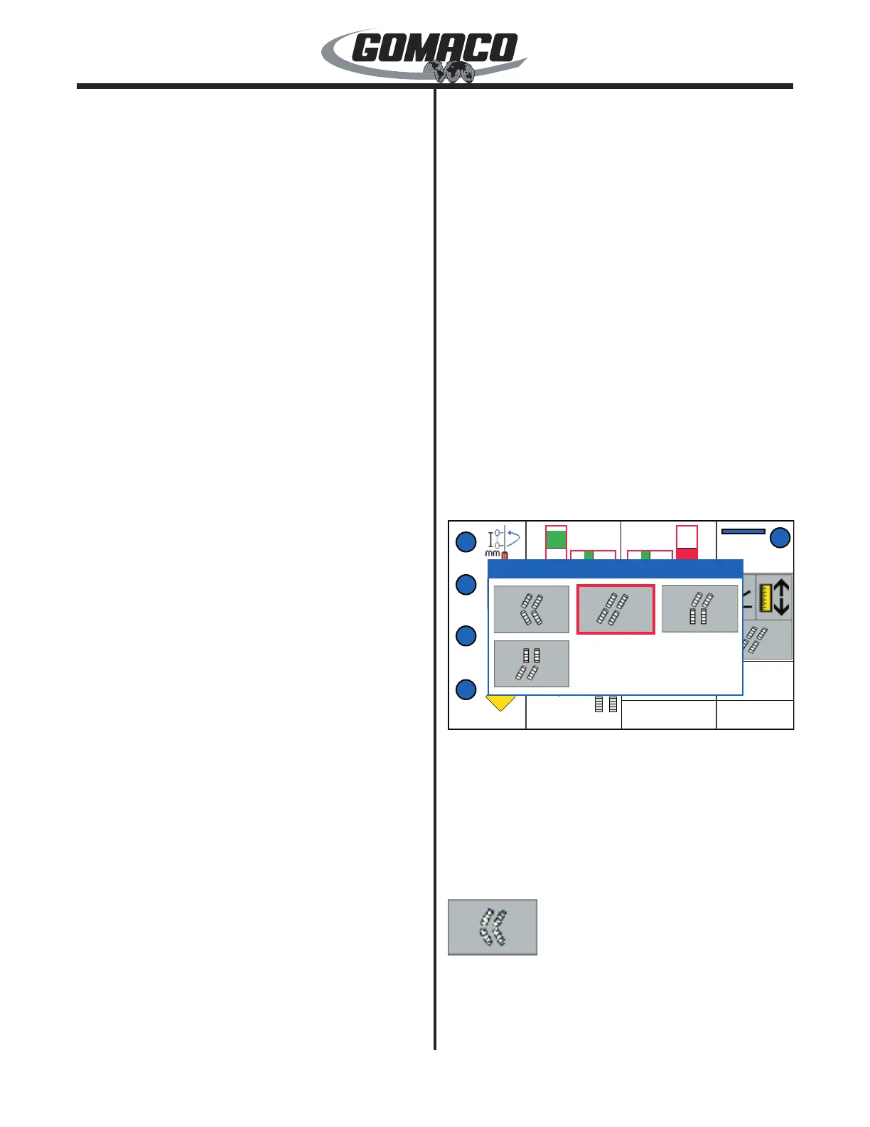
160G+
Manual Steer Mode: When selecting a manual steer
mode, the steer mode pop up display will appear as
shown. Pressing the manual steer mode select switch
(see explanation earlier) will toggle the red selection
cursor to the appropriate steering mode. When the
appropriate selection has been made, the steer mode
display will disappear from view after 2 to 3 seconds of
inactivity. The manual modes are as follows:
130
When the “coordinated steer” mode is selected, the
steering control dial will control the turning of the
tracks. The coordinated steer icon will be displayed
on the right side of the Run display panel. When
the dial is in the center position, the tracks will be
 Loading...