Commander III
2-21
straight ahead. If the dial is turned left or right from
the center position, the leading tracks will turn in the
corresponding direction and the trailing tracks will
turn in the opposite direction to give minimum turning
radius.
131
When the “crab steer” mode is selected, the steering
control dial will control the turning of the tracks. The
crab steer icon will be displayed on the right side of
the Run display panel. When the dial is in the center
position, the tracks will be straight ahead. If the dial is
turned left or right from the center position, all tracks
will turn in the corresponding direction, to walk the
machine to the side.
132
When the “front steer only” mode is selected, the
steering control dial will control the turning of the
front tracks and the rear tracks will be locked straight
ahead. The front steer icon will be displayed on the
right side of the Run display panel. When the dial is
in the center position, the front tracks will be straight
ahead. If the dial is turned left or right from the center
position, the front tracks will turn in the corresponding
direction and the rear tracks will remain straight ahead.
133
When the “rear steer only” mode is selected, the
steering control dial will control the turning of the
rear tracks and the front tracks will be locked straight
ahead. The rear steer icon will be displayed on the
right side of the Run display panel. When the dial is
in the center position, the rear tracks will be straight
ahead. If the dial is turned left or right from the center
position, the rear tracks will turn in the corresponding
direction and the front tracks will remain straight
ahead.
Automatic Steer Mode: Use the steer A/M switch to
select the automatic steer mode. The manual steer
icons will change to the selected automatic steer icon.
See the Setup Menu; Machine Setup Displays for
more information on the automatic steer mode.
038
Emergency stop indicator: The emergency stop
icon will turn red when an emergency stop switch is
pressed or a critical fault has been detected in one
of the G+ control loops. During normal operation the
icon will appear gray. Refer to the fault display for
diagnostic information when the icon is red.
062
Run/Standby indicator: The Run/Standby icon will
turn yellow when the controller is in standby mode.
The LED light in the lower corner of the display
faceplate will ash red, and the fault indicator lamp will
ash when the system is in standby mode. The icon
will appear gray, the LED light will turn green and the
fault indicator lamp will be off when the controller is in
run mode.
063
Vibrator Off/On Indicator: The vibrator icon will turn
green when the vibrator system is in the on mode.
The icon will appear gray when the vibrator system is
off. Press the vibrator A/M switch to select the on or
off mode.
287
If the setup remote is connected, the icon for the
remote will appear in the center of the display panel to
indicate that it is connected. The travel and automatic
steering/elevation functions on the main controller are
disabled.
Note: The icon will not appear if the setup remote
is disconnected.
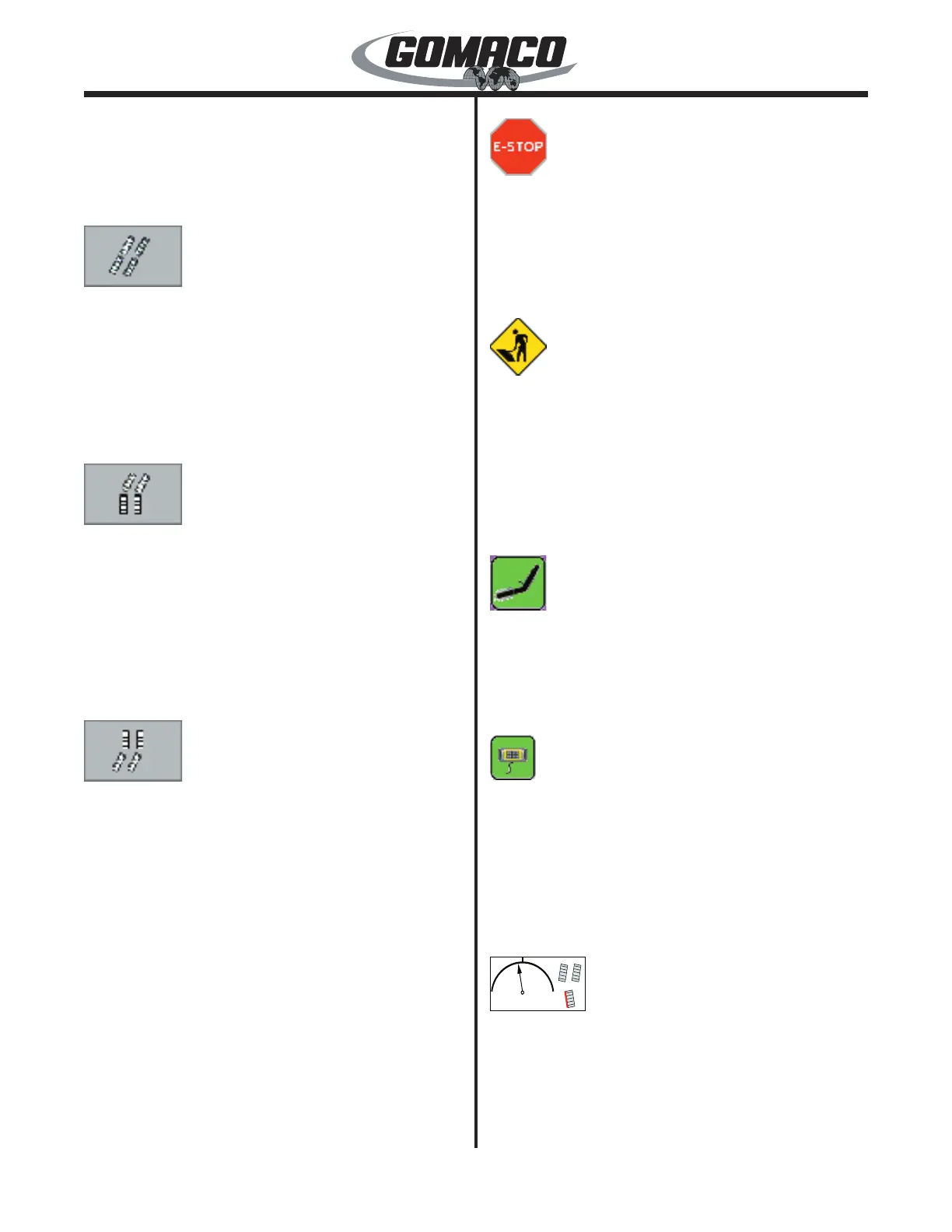
062G+
Steer Range Indicator: The steer range indicator
shows how far the tracks are turning when using the
manual steer dial. A percentage is shown from 0% up
to 100% in either direction from straight ahead. A red
line will appear to the side of any individual track icons
if a smart steer cylinder limit is reached. The track
 Loading...