Commander III
2-22
icons will steer according to the selected manual mode
and indicate corresponding track positions (three track
coordinated steer mode shown above).
Travel Indicators
065, 066, 067
FNR Indicators: The forward, neutral and reverse
indicators show the travel direction that has been
selected. The machine must be stopped and in neutral
(–) travel mode before a change in travel direction
is allowed. Press the F, N, or R switches to change
directions. The percentage of full travel speed will
be shown below the indicators and will vary from 0%
(stopped) to 100% (maximum speed).
068, 069
High/Low travel Indicator: Indicates the selected
high/low travel speed. Press the two speed switch to
change travel speeds. The machine must be stopped
and in neutral (–) travel mode before a change to high
or low speed is allowed.
Travel speed is indicated by a percentage below the
FNR indicators. Travel may vary from 0 to 100%.
Travel speed can be monitored in the feet per minute
(ft/min) section in the bottom right corner of the display.
If units are changed to the metric system, the display
will indicate meters per minute (m/min). Low speed
range for a 3-track machine is 0 to 49.0 fpm (0 to 15.0
mpm) and up to 125 fpm (38 mpm) in high speed
range. Low speed range for a 4-track machine is 0 to
37.0 fpm (0 to 11 mpm) and up to 94 fpm (29 mpm) in
high speed range.
159G+
1
2
3
4
5
A
M
M
M
A
A
0.00%
ft/min
E-STOP
~
▼
-157
-157
-151
-31
-12º
12º
-12º
-47 1000
-50
-40
The numerical deviation value will appear next to each
deviation meter when the left (◄) navigation button
is pressed. A steering sensor deviation display will
appear and the degree of track turn from straight,
for each track, will also be displayed. The elevation
deviation values will be positive for an up correction
and negative for down. The steering deviation values
will be positive for a right correction and negative for
left. The steering sensor deviation will be positive
when a right correction is required and will be negative
for a left correction. The track degree of turn will
be positive if the tracks are turned to the right and
negative if turned to the left. Press the left (◄)
navigation button again to hide the values.
063G+
1
2
3
4
5
M
A
A
M
A
A
0.00%
ft/min
E-STOP
063G+
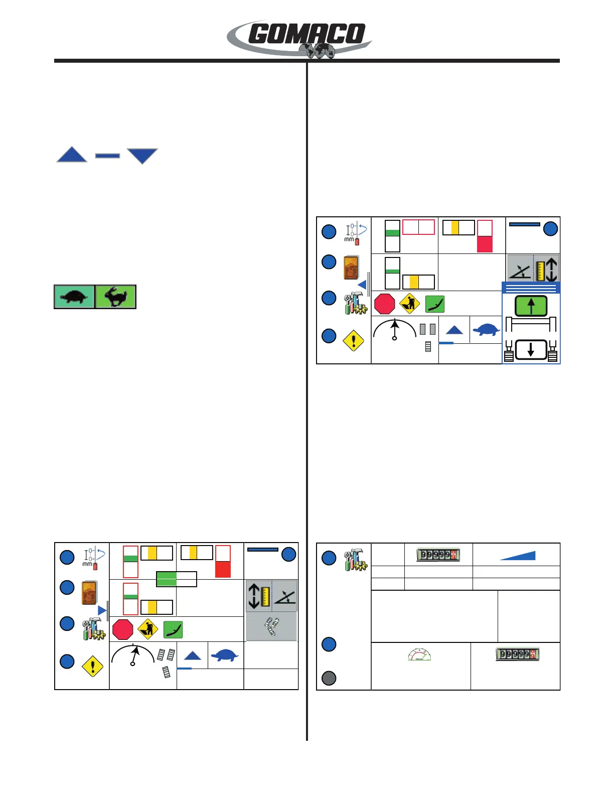
All Jog: The all jog display will appear in the lower
right corner of the run menu when the right (►)
navigation button is pressed. Press the up (▲) or
down (▼) navigation button to simultaneously raise
or lower all elevation legs on the machine. The
appropriate arrow on the all jog icon will turn green
when the corresponding navigation button is pressed.
Release the button to stop movement. The all jog
movement of each elevation leg is coordinated
through the adjustment of the elevation thresholds.
Make certain the elevation thresholds are adjusted as
described in the Maintenance chapter. Press the left
(◄) navigation button to return to the run menu.
254G+
1
3
4
0.0 0.00
E-STOP
ft/min
ft
Start
Stop
#
1
2
3.00% / -2.00%
3.00% / 3.00%
0 / 225
0 / 250
0.00 in
0.00 in
Elevation Offset
Steer Offset
 Loading...