Commander III
2-34
(determined by facing the normal paving direction)
is determined to be “front”, the “transport left” mode
should be selected. When in the transport left mode,
the left front, right front, left rear and right rear are
determined by facing the forward direction of travel
(machine traveling to the left when facing in the normal
paving direction).
069
If the right end of the machine (determined by facing
the normal paving direction) is determined to be
“front”, the “transport right” mode should be selected.
When in the “transport right” mode, the left front, right
front, left rear and right rear are determined by facing
the forward direction of travel (machine traveling to the
right when facing in the normal paving direction).
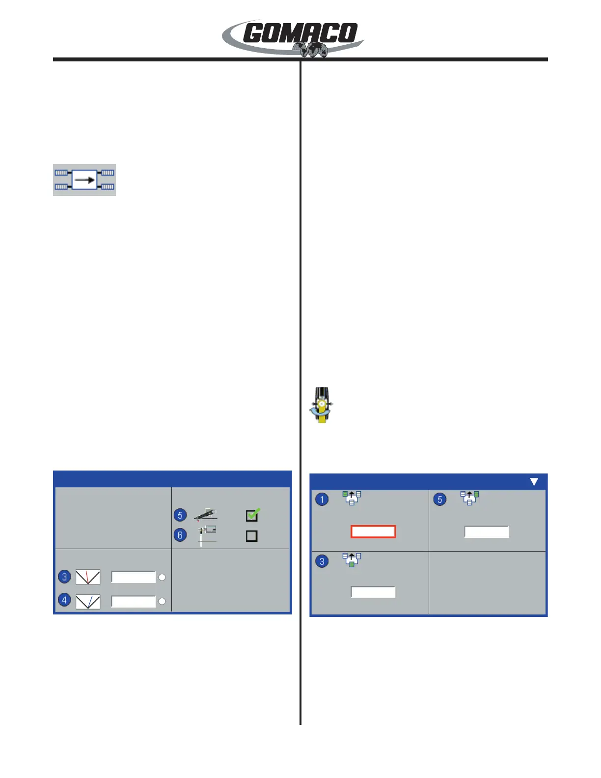
Sensor Faults: Used to set the “off stringline” sensor
fault for “on” or “off” operation. When an off stringline
fault occurs, the controller will interrupt the electrical
signal to the corresponding valve when the sensor
wand loses contact with the stringline. The elevation
sensor check box is defaulted to the “on” position with
a green check mark. Select the appropriate sensor
and use the ▲ or ▼ navigation buttons to select or
deselect the check mark in the box.
Note: Make certain the steer sensor box is
unchecked when pouring tight radii. The “off
stringline” fault may prevent the machine from
completing a satisfactory radius.
148G+
Machine Setup
Sensor Faults
Radius Assist
148G+
10
5
Radius Assist (option): The radius control valves
are an option that may be installed to assist the
machine in turning a left or right hand radius. The
number determines when the radius control valves
are activated to assist in turning tight radii to the left or
right. The red (left) icon and data value box determine
activation of the valve for an outside radius. The blue
(right) icon and data value box determines activation
of the valve for an inside radius. Adjustment range is
1 to 40. A number value of 40 will prevent the valve
from activating until the track is almost fully turned. A
number value of 1 will activate the valve as soon as
the track begins to steer. Adjust the values as needed
to facilitate radius turning capability.
Press the number button indicated in the data box to
select the setting to change. The border of the data
value box will turn red when it is selected. To change
a setting, press the ▲ or ▼ navigation buttons. Press
the OK button to store and deselect a setting. Press
the escape button (ESC) to deselect and leave a
setting unchanged. Press the escape button (ESC) to
return to the Setup Menu.
LED lights to the right of the data value box indicate
when an output signal is sent to the corresponding
radius assist valve. A green LED light indicates an
output signal to the valve and white indicates no
signal.
Note: Radius assist will appear when Machine
Type is selected as 3-track.
Setup menu
Steer Setup
070
Flashing arrows in the top right corner indicates more
displays are above or below the screen currently
viewed. Press the ▲ or ▼ navigation buttons to view.
075G+
Steer Sensitivity
12
12
075G+
12
Steer Sensitivity: Used to set the steering sensitivity
for each of the tracks. Minimum sensitivity is “1”
and maximum sensitivity is “20”. Set the steering
sensitivity for quick, smooth response and adjust as
necessary when paving has started.
 Loading...