Commander III
2-35
Note: For initial adjustment of sensitivities and
thresholds, the bump lters should be turned
“off”. Thereafter, the bump lters may be turned
“on” for ne tuning adjustment of sensitivities or
thresholds.
Press the number button indicated in the data box to
select the setting to change. The border of the data
value box will turn red when it is selected. To change
a setting, press the ▲ or ▼ navigation buttons. Press
the OK button to store and deselect a setting. Press
the escape button (ESC) to deselect and leave a
setting unchanged. Press the escape button (ESC) to
return to the Setup Menu.
076G+
Steer Thresholds
29
29
28
28
29
29
076G+
Steer thresholds display: Used to set the left and
right thresholds for the steer cylinders. The exact
procedures for setting the steer thresholds are
described in the maintenance chapter.
Press the number button indicated in the data box to
select the setting to change and an adjustment screen
will appear.
077G+
Steer Limits
0.40v
3.69v
4.65v
2.34v
077G+
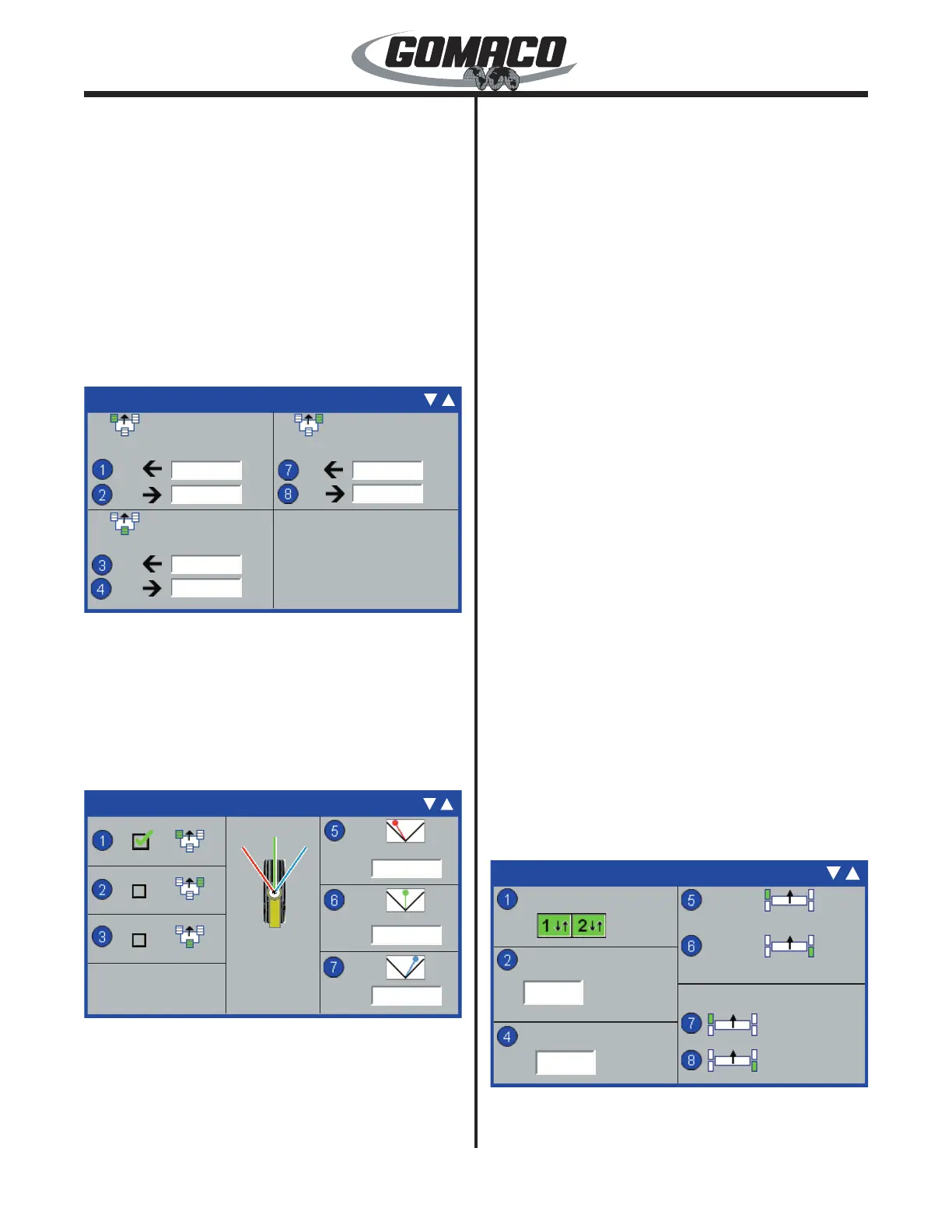
Steer Limits: From the Steer Threshold display,
depress the down (▼) button to access the Steer
Limits display. Used to set the left limit, center null
point, and right limit positions for each track. Press
the number button indicated in a data box on the left
side of the display to select a track steer cylinder for
adjustment. The selected track will display a green
check mark in the data box.
The voltage below the track icon in the center section
of the display indicates real time voltage returning from
the steering cylinder for the selected track. The track
icon and steering needles (red=left limit, green=center
or blue=right limit) are used as a reference. The track
icon and selected steering needle will rotate as the
track is turned to indicate the approximate position of
the steer cylinder.
Press the number button indicated in a data box on the
right side of the display to select the left limit, center
null point, or right limit. The border of the data value
box will turn red when it is selected. The voltage in the
selected data box will change as the track is rotated.
Press the OK button to store and deselect a setting.
Press the escape button (ESC) to deselect and leave
a setting unchanged. Press the escape button (ESC)
to return to the Setup Menu.
Two sets of limits are stored in the computer memory
when the machine is congured for 4-track operation.
When the machine is in the "pave" mode, the limits
that are set for pave are stored in memory. When
the machine is in the "transport" mode, the limits that
are set for transport are stored in memory. When the
legs are swung into one position, or the other, and the
appropriate mode is selected, the previously set limits
will be recalled.
Notice: If the legs are not returned to the same
position that the limits were previously set for,
it will be necessary to reset the limits to avoid
possible machine damage.
The exact procedures for setting the left limit, center
null point, and right limit positions for the tracks are
described in the maintenance chapter.
170G+
Heavy Steer Assist
Set ID
Set ID
Sensitivity
Sensor Null
Max Correction
Enable
170G+
-0.15˚
1.35˚
10°
30
Heavy Steer Assist (Option): Used to prevent side
to side torque on the leg assemblies caused by extra
 Loading...