Commander III
2-36
weight or misalignment of track steering components.
The display will appear when Machine Type is selected
as 4-Track Commander III. The 4-track machine will
be equipped with digital slope sensors mounted on
the left front and right rear leg assemblies. Read the
following descriptions for each section of the display.
Enable: Used to activate the Heavy Steer Assist
sensors on the machine and the phasing required
to operate correctly. The factory default setting
of (1↓↑2↓↑) is correct for sensors that are factory
installed. If sensors are eld installed in a manner
inconsistent with factory methods, select from the
remaining icons shown below and test for correct
operation. See 4-track Barrier or Paver setup chapters
for sensor installation procedures. Press the ▲ or
▼ buttons to select between the following icons as
described:
221
Sensor 1 is off - Sensor 2 is off.
222
Sensor 1 enabled normal phasing - Sensor 2 enabled
normal phasing.
223
Sensor 1 enabled with reversed phasing - Sensor 2
enabled normal phasing.
224
Sensor 1 enabled normal phasing - Sensor 2 enabled
with reversed phasing.
225
Sensor enabled with reversed phasing - Sensor 2
enabled with reversed phasing.
Sensitivity: Used to adjust the sensitivity for the
heavy steer assist system. Minimum sensitivity is “1”
and maximum sensitivity is “100”. Set the sensitivity
at 30 and adjust as necessary after paving has
started. Reaction should be quick and smooth during
operation.
Max Correction: Used to set a value for maximum
allowed degrees of steer assist correction. Minimum
adjustment is zero degrees (0°) up to a maximum of
ten degrees (10°) of rotation. A setting of 10 degrees
is the factory default.
Set ID: Used to set the location and CAN identity
codes (ID) for the heavy steer assist sensors. If heavy
steer assist sensors are added to the legs for the
first time or are replaced due to a defect, press the
appropriate number button for the sensor location and
the display will indicate “Success” when ID codes are
set.
Sensor Null: Used to set the null or relaxed position
of the heavy steer assist sensors. Press the number
button next to the sensor location icon to save the
parameter that is viewed on the display. The stored
value is used to determine when a correction to the
steering system is needed. See the Maintenance
Chapter for Sensor Null adjustment information.
309G+
Leg Ratchet
309G+
▲
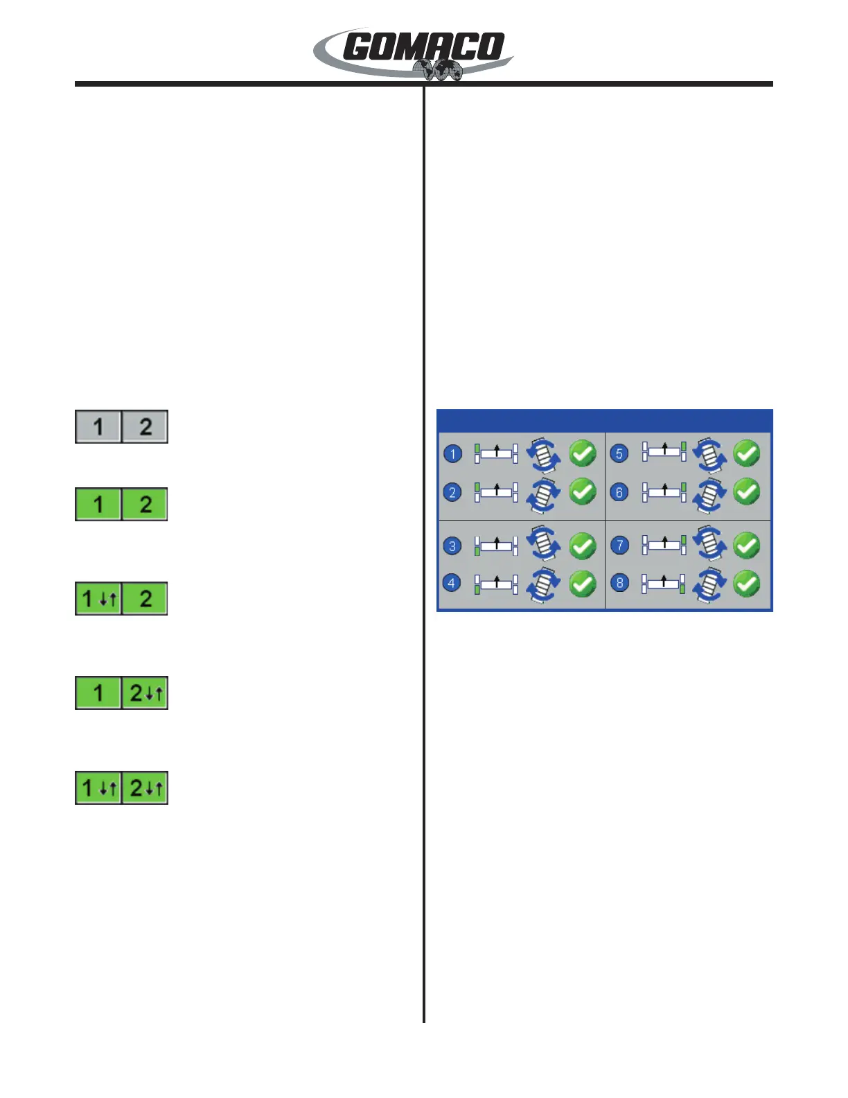
Leg Ratchet (Option): Used to rotate each track
for the 4-track paving or left transverse travel steer
modes. Each steer arm must be equipped with the leg
ratchet cylinder. The 90° leg ratchet display must be
enabled in the technician access setup displays (call
the GOMACO service department for access code
information).
Depress the steer A/M switches to select the “manual”
mode for each of the steering systems. Place the
controller in the “run” mode. Depress the 1, 3, 5, or 7
buttons to begin the transverse ratchet rotation of each
track. Depress the 2, 4, 6, or 8 buttons to begin pave
mode ratchet rotation of each track. A green check
mark will appear when the ratchet has been enabled.
The check mark will disappear when the ratchet
rotation is completed. When all tracks are rotated to
either the transverse or pave mode position, return
to the setup menu. Depress the number 1 button for
machine setup and the ▼ down navigation button until
pave mode appears. Select either the left transverse
or 4-track pave mode. Press the OK button to store
and deselect a setting. Return to the Run menu.
Depress the steer A/M switch to select the auto mode
 Loading...