22 23
Risk of material damage by inappropriate ambi-
ent conditions
>>
Keep enough space around product and to the whole
system to ensure proper ventilation and mobility.
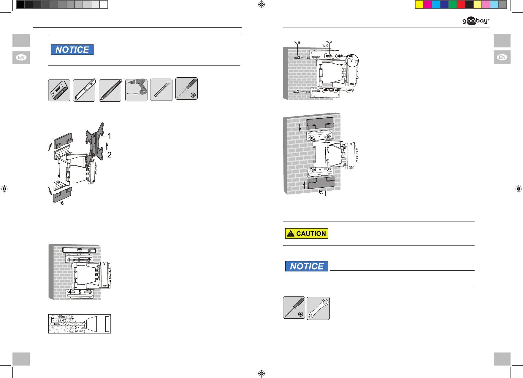
Ta b . 1 6 : Wall mounting
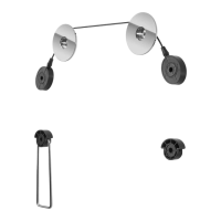
4.2.1 Preparing
1. Remove the 2 plastic covers of the
TV wall mount (A) by sliding the
upper plastic cover slopingly forwards
and upwards and the lower plastic
cover forwards and downwards.
2. Remove the VESA plate by lifting it
forwards and upwards out of its
guideway.
Make sure that the screws 1 and 2 stuck
rmlyintheVESAplate.
Fi g . 12 : Removing plastic covers and VESA plate
3. Turn the nut M8 (D) clockwise to
screw 1 about 2-3 turns until tting
loosely.
4.2.2 Implementing
1. Before drilling, attend to live cables or
other lines lying behind plaster, and
do not damage them.
2. Use a spirit level to mark the drill
holes on the wall.
3. Mark the drill holes 1 to 6 with a
pencil.
Fi g. 13: Aligning and marking
Use the wall plate (A) as template.
4. Drill the drill holes with a 10mm
concrete drill 60mm deep.
Fi g. 14: Drilling drill holes
5. Plug a concrete anchor (W-B) in each
drilling hole.
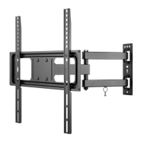
6. Attach the TV wall mount (A) with wall
screws (W-A) and washers (W-C),
that the notch of the VESA plate is
pointing upwards.
Fi g. 15 : Wall mounting
7. Reattach the plastic covers to the TV
wall mount (A).
Fig . 16: Reattaching the plastic covers
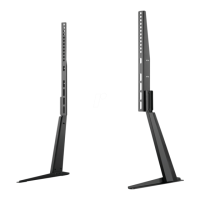
4.3 Mountingtheatscreen
Risk of injury by tripping and falling
>> Place, transport and install product, parts and acceo-
ries in a safe way.
Risk of material damage by improper procedure
>> Only use moderate force when tightening the screws
in order to avoid damaging threads.
>>
>>
NEVER set the screen on the front during installation!
Do not damage the at screen by too long screws.
Tab . 17: Mounting the at screen
1. Measure the mounting hole spacings
of your at screen.
2. Mount at screens of VESA sizes
100x100mm, 100x200mm and
200x200mm directly to the VESA
plate, like described in chapters 4.3.1
and 4.3.2.
69295 manual_V3.indd 22-23 30.05.2018 13:21:13
 Loading...