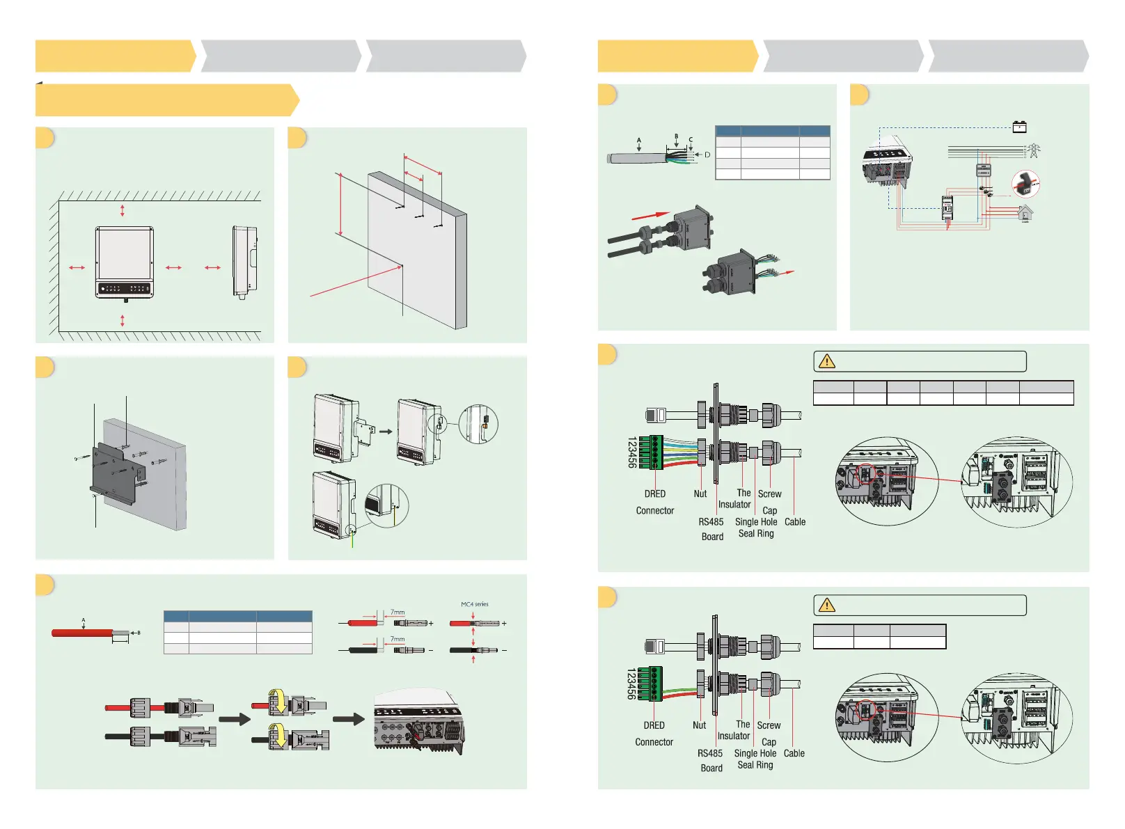
Step 1. Instrucitons for quick installation
Installation space
Upward
Downward
Front
Left and right side
Wall bracket
Self-tapping Screws
Expansion Pipe
----------------------300mm
------------------500mm
-------------------------300mm
---------200mm
A
F
H
I
G
B
C
E
D
Dimensions for drilling holes
AC Calbe:6mm
2
Copper Conductor Material
AC cable assembly and connection
DRED cable assembly
Dimensions for drilling holes
Fix the wall bracket Installation
Step1
Instructions for quick installation
Step2
SOP of battery connection
Step3
Wi-Fi configuration instruction
Step1
Instructions for quick installation
Step2
SOP of battery connection
Step3
Wi-Fi configuration instruction
UPS
UPS
UPS
UPS
Grade
A
B
C
Description
Outside diameter insulation
Conductor core section
Conductor core length
Value
5.5-8.0 mm
4-6 mm
2
7 mm
C
Note: Make sure the cables (L/N/PE) are connected to right position
Remote Shutdown
NO
Function
5
REFGEN
6
COM / DRMO
NO
Function
1
DRM1/5
2
DRM2/6
3
DRM3/7
4
DRM4/8
5
REFGEN
6
COM / DRMO
Battery wiring assembly and connection
≥300mm
≥200mm ≥200mm ≥300mm
250mm
125mm
≥500mm
240mm
4-Φ10*80mm depth
Inverter could be locked for anti-theft,
if it is needed.
Prepare the terminals and AC cables according to the left table
DRED connection is only available for Australia
and New Zealand.
Remote Shutdown is only available for Europe.
Note: 1. To battery communication cable
(Battery fails to work while communication failure)
2. To Smart Meter communication cable.
(could be extendet to max 100m)
Ground cable is needed
connecting to ground
plate on grid side
Grade
A
B
C
D
Description
Outside diameter
Separated wire length
Conductor wire length
Conductor core section
Value
13-18 mm
20-25 mm
7-9 mm
4-6mm
2
To lithium battery
Power Meter
Smart
Meter
“To Smart Meter”
Grid
CT A connect to L1
CT B connect to L2
CT C connect to L3
CT C
CT B
CT A
battery
 Loading...