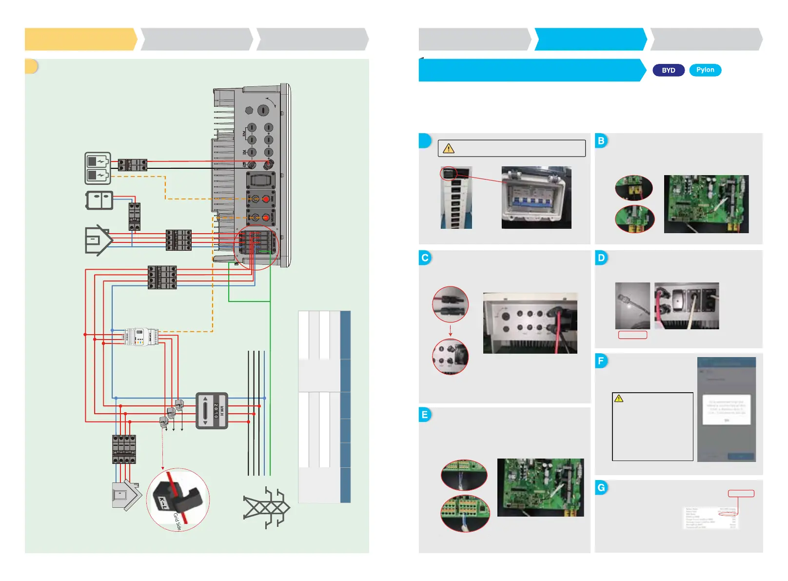
WIRING SYSTEM FOR BT SERIES HYBRID INVERTER
OFF
ON
CT C
CT B
CT A
GW5K-BT
Please select Breaker according to the specification below
25A/400V AC breaker
25A/400V AC breaker
32A/400V AC breaker
32A/400V AC breaker
GW6K-BT
GW8K-BT
GW10K-BT
①
①
②
②
③
③
④
④
⑤
⑤
40A/600V DC
breaker
Depends on
household
loads
1. For batteries with attached breaker, the external DC breaker could be omitted.
2. Please use CT A for L1, CT B for L2 and CT C for L3. And follow “House(K) →Grid(L)”
direction to do the connection. Otherwise there will be an error reminded by APP.
For BYD Battery-Box H6.4 / 7.7 / 9.0 / 10.2 / 11.5 with BT inverter
Note: In the gridless area, battery does not support off-grid applications. (There will be no further notice if this entry is subject to change)
Battery
To Battery
AC Breaker
DC Breaker
AC Breaker
AC Breaker
Loads
Grid
PE
N
L3
L2
L1
“To Smart Meter”
AC Breaker
SmartMeter
AC Breaker
1-phase
Loads
3-phase
Loads
Note: This diagram indicated wiring structure of BT series AC coupled
inverter, not the electric wiring standard.
Communication OK
EIA/TIA568B
J
A
Step 2. SOP of Battery connection with BT inverter
1. BYD
Step1
Instructions for quick installation
Step2
SOP of battery connection
Step3
Wi-Fi configuration instruction
Step1
Instructions for quick installation
Step2
SOP of battery connection
Step3
Wi-Fi configuration instruction
Note: This manual only tells connection methods between battery and GoodWe inverters. Other operations on battery, please refer to battery user
manual. (This Quick Reference only includes parts of batteries, if there is a subsequent increase in battery, there will be no further notice.)
Make sure that the inverter and battery pack is turned
off before connecting the battery pack to the inverter.
Connect the other end of the power cable to the terminal
block of the hybrid inverter.
The other end of “To Battery” cable should be connected to
CAN port of BYD BMU box. Before this, you should pick out
the blue-white life and the blue line. Then, connect the
blue-white line to the second hole site, and connect the blue line
to the third hole site.
BYD Battery Setting: You should
set “Series Battery Counts” and
“Invert” (GoodWe) correctly
through BYD WiFi of Ethernet.
(Refer to BYD QUICK
REFERENCE GUIDE to connect
WiFi or Ethernet)
On PV Master, you should choose
the right battery type used in your
system by “Battery Model” selection
or battery communication will fail.
After all connections and
settings are done, please
check if battery
communication is OK on
PV Master→ Param →
BMS Status, which should
be “Communication OK”
The communication cable for battery is attached on the
inverter, Please use this cable as battery communication
cable.
To connect the cables coming from the inverter to the BYD battery pack,
take the following steps.
Connect the power cables to the terminal block of BYD battery
management unit (BMU).
Connect the negative cable to “P-” and the positive cable to “P+”.
 Loading...