Product Introduction
7
User Manual V1.0-2022-03-22
3.4 Appearance
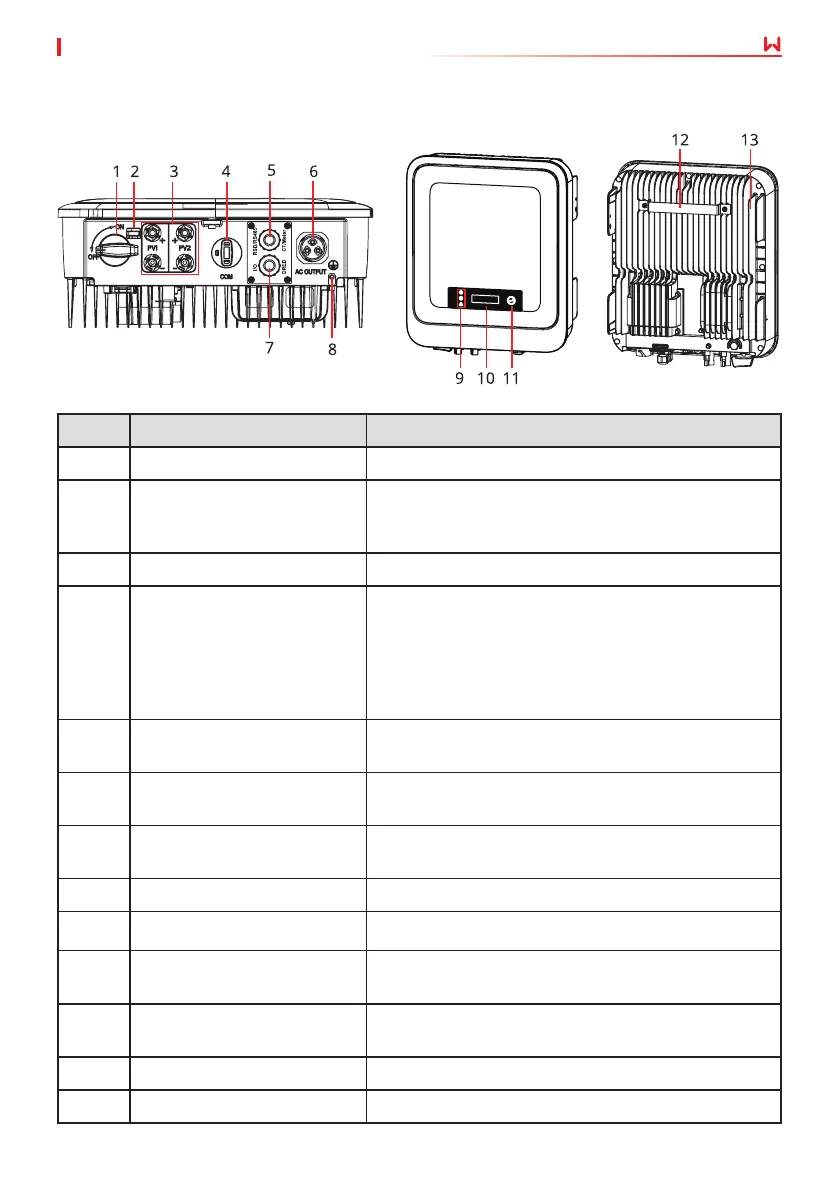
3.4.1 Parts
No. Parts Description
1 DC Switch Start or stop DC input.
2 DC Switch Lock
Only for Australia. Turn the DC switch to OFF and
lock it to avoid electric shock when you have to work
on the inverter.
3 PV Input Terminal Used to connect the PV module DC input cables.
4
COM Port for communication
module, USB-RS485 cable or
USB.
• Connect a communication module like Bluetooth,
WiFi/LAN, WiFi, GPRS, 4G, etc. The module type
may dier depending on actual needs.
• Connect the USB-RS485 cable in Brazil.
• Update the software version of the inverter using
a USB ash driver.
5
COM Port for RS485, remote
shutdown, meter, or CT.
Used to connect the RS485, meter, CT, or remote
shutdown communication cable.
6 AC Terminal
Used to connect the AC output cable, which connects
the inverter and the utility grid.
7
COM Port for DRED or dry
contact.
Reserved port. Used to connect the DRED cable or
dry contact cable.
8 Grounding Point Used to connect the PE cable.
9 Indicator Indicates working state of the inverter.
10 LCD (optional)
Optional. Used to check the parameters of the
inverter.
11 Button (optional)
Optional. Used to select menus displayed on the
screen.
12 Mounting Plate Used to install the inverter.
13 Heat sink Used to cool the inverter.
 Loading...