display an error message. Refer to Table 4.3.
Through key operation, the screen can display different information such as operation
parameters and power generation status in this area. There are two levels of menus, and
the flow chart of first level menu is shown below:
(3) Use of the display
There are 2 modes of button operation: short press and long press.
(4) Use of the display and LCD display
The display allows accessing the configuration of the basic parameters. All the language,
All the language, time and country setting can be configured by buttons. The menu, shown
in the LCD display area has two levels of menu. Short and long key presses will take you
between menus and through each menu. Items in the first level menu that have no second
level are locked. For these items, when the key is pressed for two second, the LCD will
display the word“ Lock ”followed by data relating to the first level menu item. The
locked menu can only be unlocked under system mode switching, fault occurrence or key
operation.
In all levels of menu, If no action is taken for 20 seconds, the backlight of the LCD display
will switch off, the display will automatically revert to the first item of the first level menu,
and any modifications made to the data will be stored into internal memory.
(5)Menu Introduction
• When the PV panel is feeding power to the inverter, the screen shows the first-level menu.
• The initial display is the the first item of the first level menu, and the interface displays the
current status of the system, It shows“ Waiting Pac=0.0W ” in the initial state; it
shows “ Normal Pac=6000.0W ”during power generation mode; if there is something
wrong with the system, an error message is shown. Please refer to chapter 5.
View PV voltage, PV current, grid voltage, current and frequency:
• Short press the key to enter the E-Today menu which display the total power generation
for today.
• Short press the key to enter the E-Total menu which display the total power generation
for Until today.
• Short press the key to enter the Vpv menu which display the PV voltage in “V”.
• Short press the key to enter the Ipv menu which display the PV current in “A”.
• Short press the key to enter the Vac menu which display the grid voltage in “V”.
• Short press the key once more to enter the Iav menu which display the grid current in
“A”.
• Short press the key once more to enter the Frequency menu which display the grid
frequency in HZ.
• View Error massage
Short press the key once more to enter the Error Massage History menu.
Long press(2s)the key to enter the second level menu of error detection. The last three
inverter error massage will be shown by short pressing the key in this second level menu.
4.2 User interface and use of the display
Set Safety Country:
If display shows“ GW6K-DT Pac=6000.0W ”, then long press (2S) the key to enter the
second level menu. Short press to browse the safety country available. Please waiting for 10s
after choose suitable safety country ,then display will show“setting...” and jump to“ Set
OK ”or“Set Fail”.
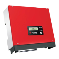
(1) A schematic of the display screen is shown as below:
Display area is divided as follows:
(2) Display area
Line 1---Working status information
This area displays the status information.“ Waiting Pac=0.0W ”indicates the inverter is
standby for power generation;“ Checking**S Pac=0.0W ” (checking time is based on
safety, and varies from country to country) indicates the inverter is self-checking, counting
down and preparing for power generation.“ Normal Pac=6000.0W ”indicates the
inverter is generating power. If any condition of the system is abnormal, the screen will
4 System Operation
4.1 Indicator Lights
Indicator lights in Yellow/Green/Red correspondently refer to
ON = WiFi CONNECTED / ACTIVE
BLINK 1 = WiFi SYSTEM RESETTING
BLINK 2 = WiFi ROUTER PROBLEM
BLINK 4 = WiFi SERVER PROBLEM
OFF = WiFi NOT ACTIVE
ON = INVER TER IS FEEDING POWER
OFF= INVER TER IS NOT FEEDING POWERATTHE MOMENT
ON = FAULT OCCURRED
OFF = NO FAULT
Normal
Pac=6000.0W
Line 1
Line 2
POWER
RUN
FAULT
1211
 Loading...